
System and method for managing load distribution across a power grid

a technology for managing load and power grid, applied in power network operation system integration, electrical generators, transportation and packaging, etc., can solve problems such as increased regional or local overload, and increase the risk of local distribution transformer overload, so as to prevent uncontrollable load on transformers and prevent damage to electrical grid

Active Publication Date: 2015-05-26
TRILLIANT NETWORKS
View PDF607 Cites 23 Cited by
  • Summary
  • Abstract
  • Description
  • Claims
  • Application Information

AI Technical Summary

Benefits of technology

This system effectively stabilizes the power grid by preventing transformer overloads, minimizing the risk of damage, and accommodating varying PEV charging scenarios, ensuring efficient and controlled charging that extends transformer lifespan and reduces the need for costly upgrades.

Problems solved by technology

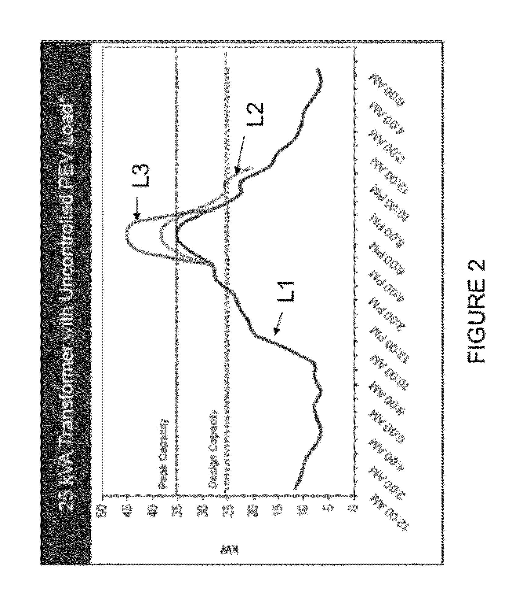
Unfortunately, as the number of PEVs on the road continues to increase, the risk of overloading local distribution transformers also increases.
Accordingly, overloading problems may arise when several PEVs in the same neighborhood recharge at the same time, or during the normal summer peak loads.
At each tier there is a risk of overloading (regional or local) if the dynamic behavior is not well monitored.
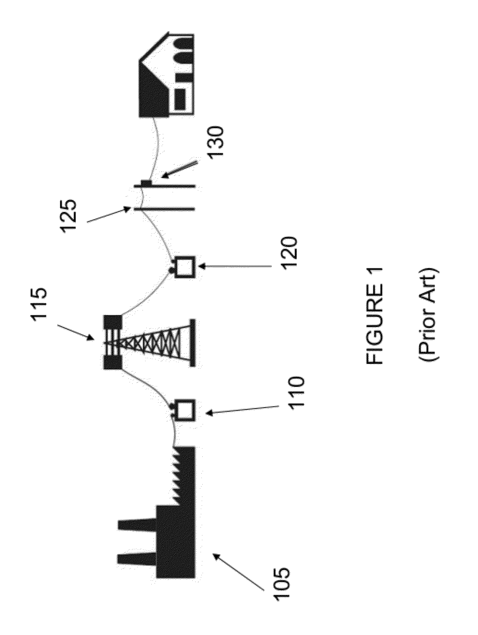
If one or more homes mapped to a particular distribution transformer 130 adds a particularly large load, such as a PEV, this may increase the risk of overloading the mapped distribution transformer.
However, mass replacements are expensive and could be prohibitively so in the case of expected PEV strain.
Further, such replacements / upgrades would be wasteful in many cases, where current transformers were or would have been sufficient to meet demand.
Further still, replacement / upgrades may be insufficient to meet booming demand.
However, this would not mitigate immediate transformer load concerns.
However this may not always be easy to manage, and does not consider the scenario of charging away from home.
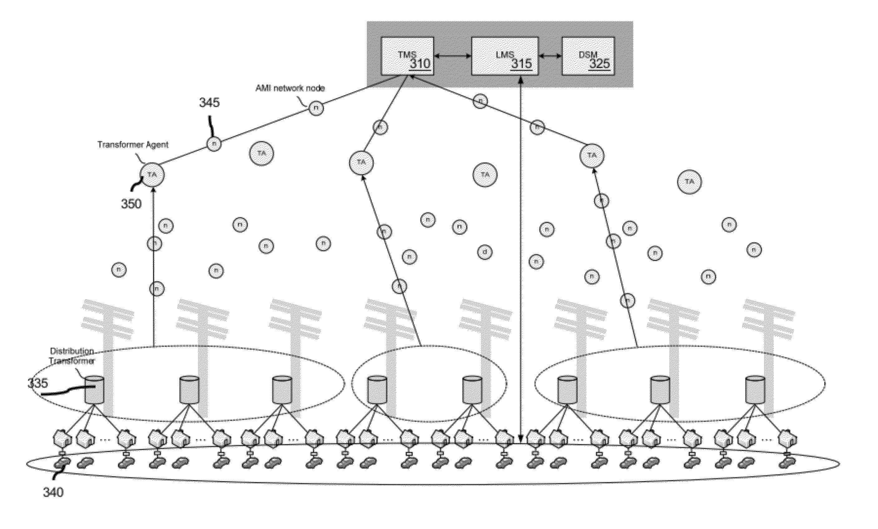
Further, load limitations discussed above may be localized to a (static) transformer and may be difficult to manage from an ultimate utility head-end without visibility to the instantaneous / accumulated load per transformer.

Method used


Image

  • System and method for managing load distribution across a power grid
  • System and method for managing load distribution across a power grid
  • System and method for managing load distribution across a power grid

Examples


Embodiment Construction

[0038]The embodiments and examples presented herein describe systems and methods for preventing power transformer and / or electrical system overloads via admission control mechanisms. The systems and methods described herein may prevent a transformer's load from exceeding a predetermined load threshold. Scheduling PEV charging events by considering instantaneous and / or historical load state of an associated transformer may minimize the risk of the transformer exceeding its peak capacity. Moreover, controlled charging may also help minimize accelerated aging of a transformer. It will be appreciated that, although embodiments specifically refer to admission control of PEV charging scenarios, the invention is not necessarily limited as such, and any embodiment may be generalized to one or more electrical devices requiring electrical load.

[0039]Referring to FIGS. 3a and 3b, different actors and interactions involved with PEV charging as part of a smart grid system (e.g., Advanced Meterin...


PUM

PropertyMeasurementUnit
charge rateaaaaaaaaaa
voltageaaaaaaaaaa
frequencyaaaaaaaaaa

Abstract

A method for scheduling a charge of a plug-in electric vehicle (PEV) includes receiving, by a load management system, PEV information from a PEV plugged into an electric vehicle supply equipment (EVSE); transformer information from a transformer management system, the transformer information relating to a transformer associated with the EVSE; determining, by the charging information based on the PEV information and transformer information; providing the charging information to the PEV.

Description

CROSS-REFERENCE TO RELATED APPLICATIONS[0001]The present application claims the benefit of similarly titled U.S. provisional patent application Ser. No. 61 / 450,277, filed Mar. 8, 2011, which is incorporated herein by reference in its entirety.FIELD OF THE INVENTION[0002]The present invention is generally directed to managing a load of one or more transformers in an electricity transporting grid to enable controlled growth of charging plug-in electric vehicles demands beyond a reserved load of supported homes.BACKGROUND[0003]Pollution-related concerns, coupled with high gasoline prices, increased political tension with the worlds' largest petroleum suppliers, and increasing government support have lead to increased demand for electric vehicles. It is estimated that 10 to 12 carmakers are ready to launch plug-in models by 2015, and the electric vehicle market is expected to grow to over 2.5 million cars by the same year. Such electric vehicles include, for example, plug-in electric ve...

Claims


Application Information

Patent Timeline
Patent Type & Authority Patents(United States)
IPC IPC(8): H01M10/46B60L11/18H02J7/00
CPCH02J7/0013B60L11/1844Y02T10/7088Y02T10/7005Y02T90/163Y02T90/14Y02T90/128Y02T10/7055Y04S10/126Y02E60/721Y04S30/12Y02T10/7072B60L53/63H02J2310/48H02J2310/60H02J3/14Y02E60/00Y02T10/70Y02T90/12Y02T90/167Y04S20/222Y02B70/3225H02J2310/64Y04S30/14Y02T90/16
Inventor BEMMEL, VINCENTCONANT, ROBERT
Owner TRILLIANT NETWORKS
Learn More