This helps you quickly interpret patents by identifying the three key elements:
Problems solved by technology
Method used
Benefits of technology
Benefits of technology
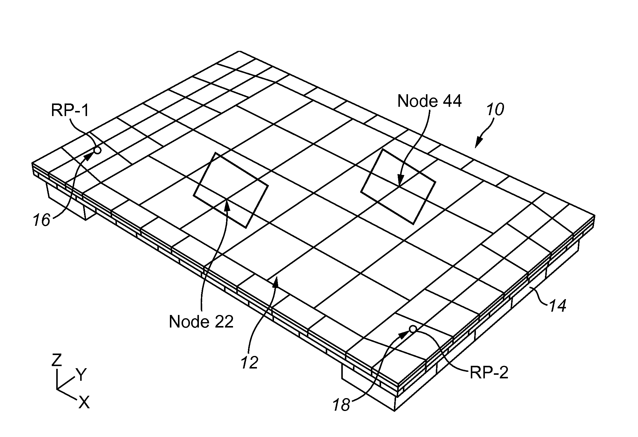
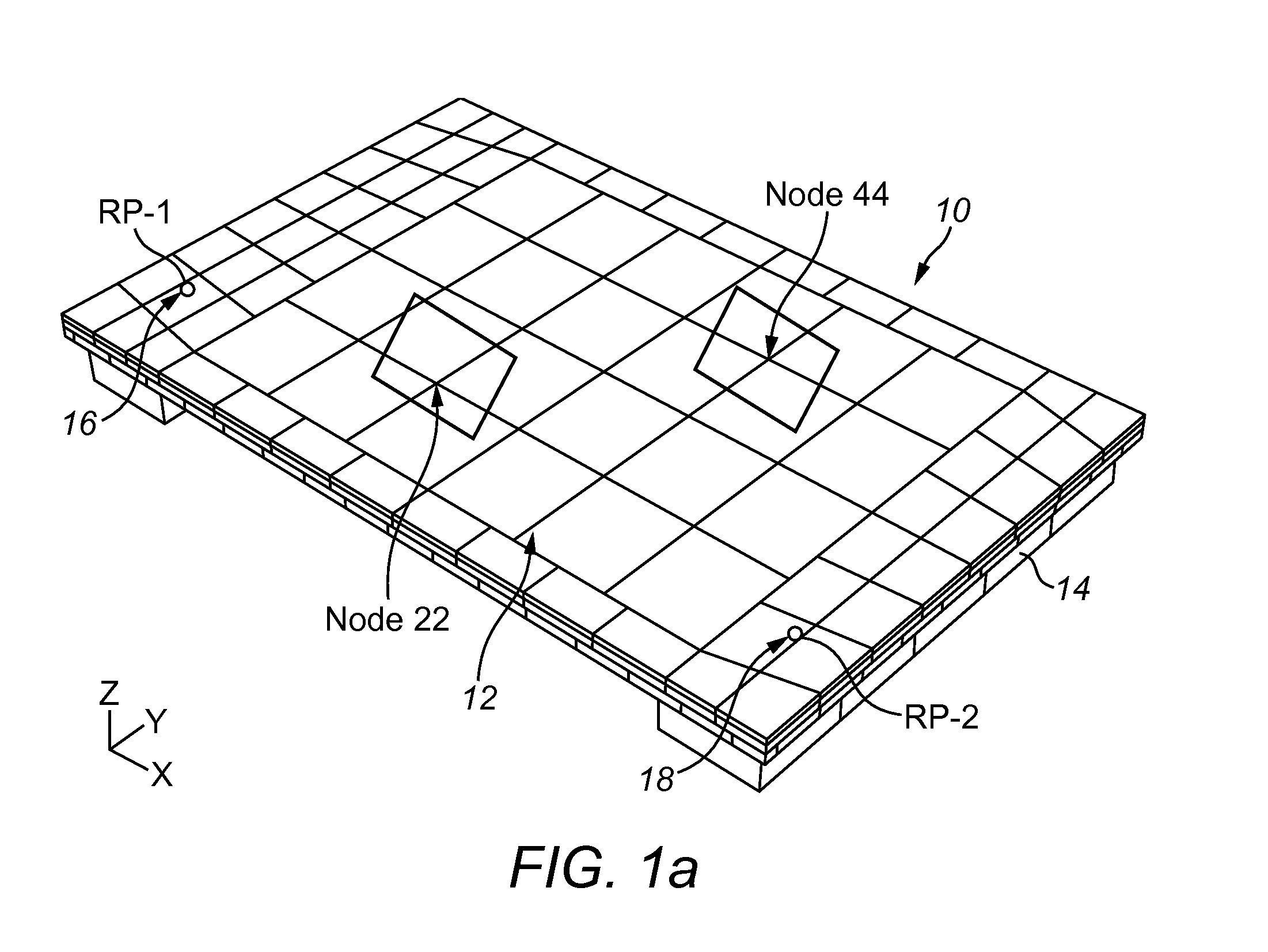
The invention is a touch-sensitive device that uses bending waves to provide tactile feedback to the user through a panel. The device has a touch-sensitive screen with multiple sensing areas and vibration exciters that apply bending waves to the panel in response to user touch. The device also includes signalprocessing means that apply signals to the vibration exciters to maximize the amplitude of the bending waves at the sensing area being walked on and reduce it at other areas. Additionally, the invention provides an option to have n or more vibration exciters to achieve an optimal solution. The device can also be designed to reduce crosstalk between the sensing areas and improve the haptic response. Overall, the invention provides a more immersive user experience through touch and vibration feedback.
Problems solved by technology
Anywhere else on the panel will experience a combination of the signals, but this is unimportant.
Method used
Image
Click on the blue label to locate the original text in one second.
Reading with bidirectional positioning of images and text.
Examples
example 1
m=3, n=2
Output 1 transfer admittances: P1_1=0.472+0.00344j Output 2 transfer admittances: P1_2=−0.206−0.195j
Output 1 transfer admittances: P2_1=0.479−0.129j
Output 2 transfer admittances: P2_2=0.262+0.000274j
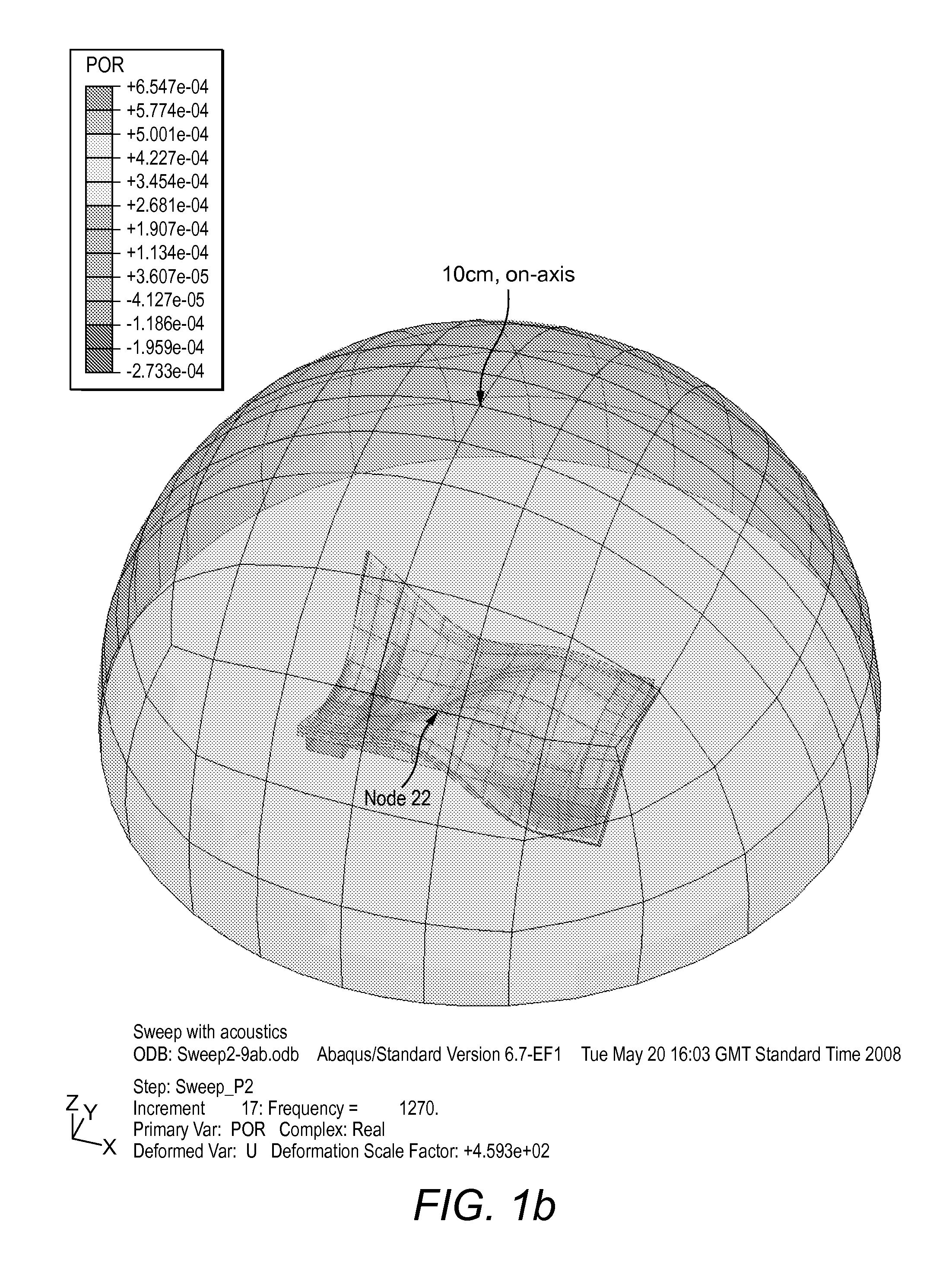
[0197]Actually, we solve just the acoustics problem, then do the rest all at once. That way, the acoustics problem is solved exactly.
Eigenvalues(M1)=0, 0, 10.714
V1=(0.770−0.199j, 0.376+0.202j, 0.377+0.206j)
V2=(0.097−0.071j, 0.765+0.010j, −0.632+0.0016j)
[0198]As V1 and V2 both correspond to a zero eigenvalue, a·V1+b·V2 is also an eigenvector corresponding to a ze...
PUM
Abstract
A touch sensitive device comprising a panel capable of supporting bending waves, a user-accessible touch sensitive screen on or forming part of a face of the panel, the touch sensitive screen having a plurality of different sensing areas, a plurality of vibration exciters coupled to the panel to apply bending waves to the panel to provide tactile feedback at the plurality of sensing areas in response to the user touching a sensing area, and signalprocessing means arranged to apply signals to the vibration exciters so as to steer bending waves applied to the panel by the plurality of vibration exciters whereby the amplitude of the applied bending waves is maximized at the sensing area touched by the user and reduced or minimized at each other sensing area.
Description
BACKGROUND OF THE INVENTION[0001]1. Field of the Invention[0002]The invention relates to touch sensitive devices including touch sensitive screens or panels.[0003]2. Description of Related Art[0004]U.S. Pat. No. 4,885,565, U.S. Pat. No. 5,638,060, U.S. Pat. No. 5,977,867, US2002 / 0075135 describe touch-operated apparatus having tactile feedback for a user when touched. In U.S. Pat. No. 4,885,565 an actuator is provided for imparting motion to the CRT when the actuator is energised to provide tactile feedback. In U.S. Pat. No. 5,638,060, a voltage is applied to a piezo-electric element which form a switch to vibrate the element to apply a reaction force to a user's finger. In U.S. Pat. No. 5,977,867, a tactile feedback unit generates a mechanical vibration sensed by the user when the touch screen is touched with a finger or a pointer. The amplitude, vibration frequency and pulse length of the mechanical vibration are controlled, with the pulse width being long enough to be felt but sh...
Claims
Application Information
Patent Timeline
Application Date:The date an application was filed.
Publication Date:The date a patent or application was officially published.
First Publication Date:The earliest publication date of a patent with the same application number.
Issue Date:Publication date of the patent grant document.
PCT Entry Date:The Entry date of PCT National Phase.
Estimated Expiry Date:The statutory expiry date of a patent right according to the Patent Law, and it is the longest term of protection that the patent right can achieve without the termination of the patent right due to other reasons(Term extension factor has been taken into account ).
Invalid Date:Actual expiry date is based on effective date or publication date of legal transaction data of invalid patent.

