Video switch

a video switch and switch technology, applied in the field of video switches, can solve the problems of time-consuming and complicated connection to a tv to display your laptop, and achieve the effect of quick connection

Active Publication Date: 2015-05-26
HAWORTH SPA
View PDF74 Cites 15 Cited by
  • Summary
  • Abstract
  • Description
  • Claims
  • Application Information

AI Technical Summary

Benefits of technology

[0003]The present invention in accordance with the current embodiment provides a video switch system capable of enabling users to quickly connect, present information, have a video conference, or a multi-user wireless video session, or a combination thereof, in a collaborative manner.
[0008]In one embodiment, the present invention may allow for great flexibility in both applications and installation. It may also include a power and data hatch with a touch sensitive interface to allow for video signal and mode control.
[0009]In one aspect, the present invention provides an effective and adaptable system for enabling users to collaborate or share information on one or more monitors. The system may include a modular interface capable of being adapted to accept a variety of video sources such that the system may provide a standardized interface for various equipment types, and may be upgraded to communicate with additional or different video interfaces.

Problems solved by technology

This process of connecting to a TV to display your laptop may be time consuming and overly complicated.

Method used


Image

  • Video switch
  • Video switch
  • Video switch

Examples


Embodiment Construction

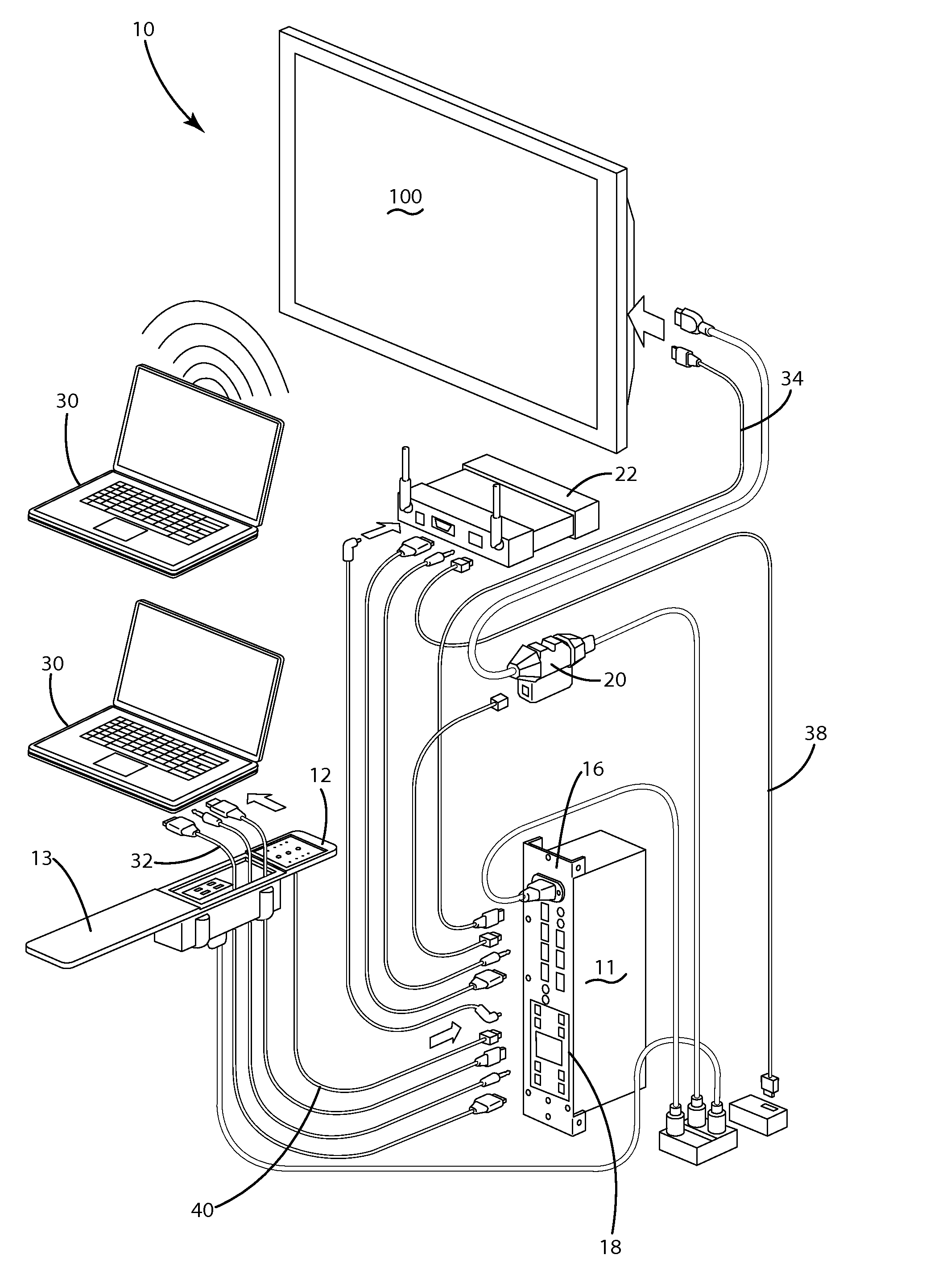
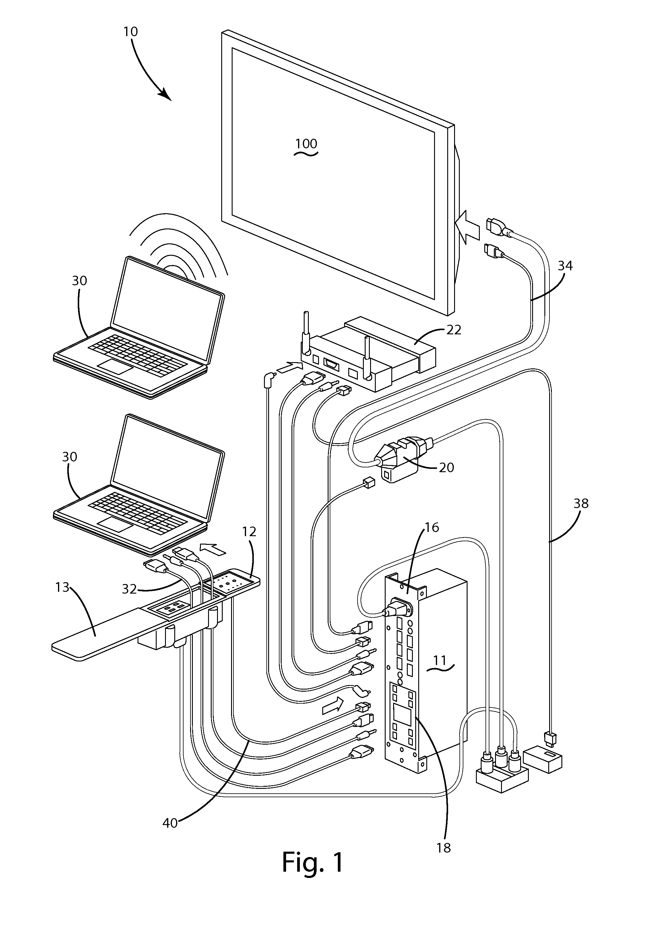
[0023]A video switch system according to one embodiment of the present invention is shown in FIGS. 1-12 and generally designated 10. The video switch system 10 may include a switching unit 18 that coordinates displaying information on the monitor 100. The switching unit 18 may operate by taking signal sources from various devices, such as a laptop 32 or a wireless presentation system 22, and cables 32 and directing one or more of the signal sources through one signal cable 34 to a TV or monitor 100, as shown in the illustrated embodiments of FIGS. 1 and 2. This may be accomplished by first connecting a source device, such as a laptop 30, to a cable 32 that comes out of a hatch 13 (shown in further detail in the illustrated embodiments of FIGS. 3-4 and 9). The cable 32 of the hatch 13 may connect to a modular video / audio input card 14 (shown in the illustrated embodiments of FIGS. 5 and 6) which is, in turn, connected to a switching unit 18 (shown in further detail in the illustrated...


PUM


Abstract

A video switch system providing a collaborative environment for one or more users to share information. In the current embodiment, the video switch system enables users to quickly connect to the system, present information, have a video conference, or have a multi-user wireless video session, or a combination thereof, in a collaborative manner.

Description

BACKGROUND OF THE INVENTION[0001]The present invention relates to systems for routing video signals from varying sources to one or more displays in a working, collaborative environment.[0002]Generally, when people want to connect to a monitor or TV screen to present from their laptop, they will use a video cable. There are a few different types of cables and associated ports for them on both TVs and laptops, so the user may want to make sure they have the right cable and ports available to connect to the monitor or TV screen. They may also want to use the TV remote to power on the TV, as well as to select the correct port. With this conventional system, if more than one person would like to present, they would need to unplug the cable from the original laptop and plug it into their laptop, assuming they have the right port to accept it. This process of connecting to a TV to display your laptop may be time consuming and overly complicated.SUMMARY OF THE INVENTION[0003]The present inv...

Claims


Application Information

Patent Timeline
Patent Type & Authority Patents(United States)
IPC IPC(8): H04N5/268H04N7/14G06F3/00H01J3/22
CPCH04N5/268G06F3/04842G06F3/04847G06F3/0488H04N7/142H04N7/148H04N7/15
Inventor MCCLYMONDS, RYAN J.SNAVELY, ERIC B.LIPSKY, STEFFENWAYNER, ROBERT C.KING, STEVEN J.PATE, RANDELL E.WARWICK, TIMOTHY J.YOUNG, PATRICK E.
Owner HAWORTH SPA
Why Eureka
Try Eureka