Method and apparatus for the dialysis of blood

a technology of dialysis and blood, applied in the field of blood dialysis, can solve the problems of reducing the efficiency of hemodialysis, requiring repetitive access to hemodialysis treatment, and dialysis sessions would need to increase significantly in duration and/or frequency, so as to minimize the possibility of recirculation of dialyzed blood, reduce the possibility of clot removal, and minimize the effect of recirculation

Active Publication Date: 2015-06-02
MEDICAL COMPONENTS INC
View PDF54 Cites 8 Cited by
  • Summary
  • Abstract
  • Description
  • Claims
  • Application Information

AI Technical Summary

Benefits of technology

[0021]The present invention provides a novel method and apparatus for the dialysis of blood. Among other things, the present invention comprises the provision and use of a novel hemodialysis catheter which is configured to minimize the aforementioned undesirable recirculation of dialyzed blood, yet which allows its lumens to be interchangeably used for suction or return functions. The novel hemodialysis catheter is also designed to minimize the possibility of the catheter inadvertently adhering to vascular walls, and to simplify removal of any clots which might form adjacent to the distal end of the catheter. And the novel hemodialysis catheter is easy to manufacture and inexpensive to produce.

Problems solved by technology

Thus, hemodialysis treatments require repetitive access to the vascular system of the patient.
As a result, there would be a significant reduction in the efficiency of a hemodialysis procedure (e.g., 15-30%, depending on the catheter tip design), and hence dialysis sessions would need to increase significantly in duration and / or frequency.
Furthermore, if such a line reversal were to occur inadvertently and escape the attention of the attending medical personnel, the reduced hemodialysis efficiency might cause a patient to unknowingly receive inadequate dialysis during a treatment session, which could have serious health consequences for the patient.
The requirement that each line be dedicated to a particular function (i.e., suction or return, depending on whether its mouth is disposed proximal or distal to the mouth of its counterpart line) can be problematic in certain situations.
As noted above, such line reversal is problematic where the hemodialysis catheter utilizes the aforementioned “staggered tip” construction.
However, as noted above, such line reversal is problematic where the hemodialysis catheter utilizes the aforementioned “staggered tip” construction, since the mouth of the suction line should be disposed upstream of the mouth of the return line in order to minimize the recirculation of dialyzed blood.
However, in a conventional application of this side-by-side construction, hemodialysis efficiency is greatly reduced, since the mouth of the return line is no longer disposed distal to the mouth of the suction line, and hence there is a much higher likelihood that cleansed blood exiting the return line will be immediately drawn back into the suction line of the dialysis catheter, thereby resulting in the undesirable recirculation problem discussed above.
Furthermore, where the mouths of the two lines are disposed in a side-by-side configuration such as that shown in FIG. 3, suction from the suction line may cause the distal tip of the hemodialysis catheter to adhere to a vascular wall (see, for example, FIG. 4), which can also greatly reduce catheter efficiency.
However, since these side holes are smaller in size than the mouth of the suction line, they are incapable of supporting normal catheter flow rates and hence catheter flow rates are still greatly reduced.
Prior art hemodialysis catheters also tend to suffer from various additional deficiencies.
This is because the distal end of the hemodialysis catheter is disposed in a turbulent blood environment, and some of the catheter lock solution inevitably leaks out of the distal end of the hemodialysis catheter and is replaced by blood, which can then clot at the distal end of the hemodialysis catheter.
These blood clots can be difficult and / or time-consuming to remove, thereby slowing down dialysis set-up and / or reducing dialysis throughput.
In this respect it should be appreciated that blood clot removal can be particularly difficult where side windows are formed adjacent to the distal ends of the lumens of the hemodialysis catheter, since portions of the blood clots may extend through the windows and thereby mechanically “lock” the blood clots to the hemodialysis catheter.

Method used


Image

  • Method and apparatus for the dialysis of blood
  • Method and apparatus for the dialysis of blood
  • Method and apparatus for the dialysis of blood

Examples


Embodiment Construction

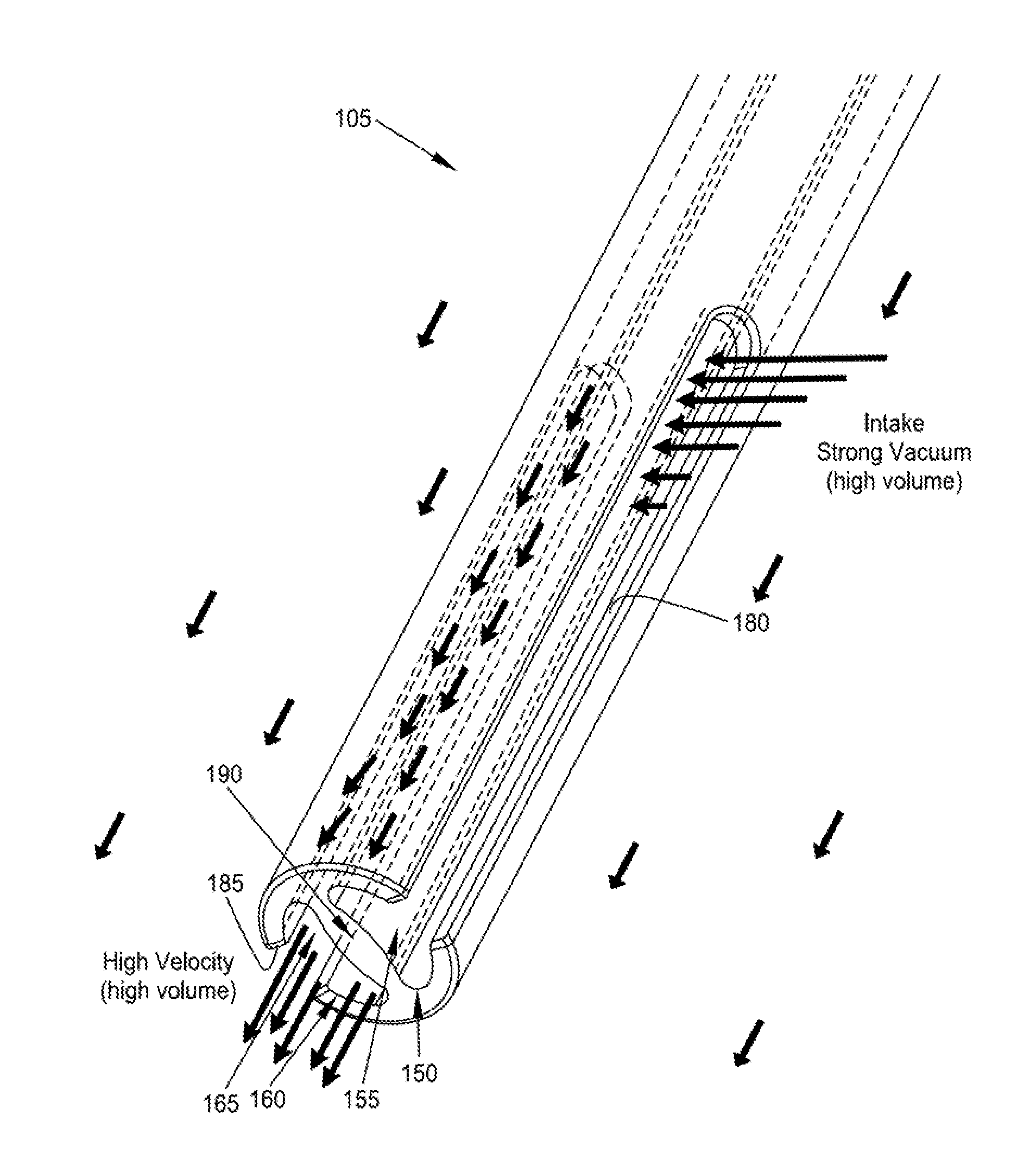
[0085]The present invention provides a novel method and apparatus for the dialysis of blood. Among other things, the present invention comprises the provision and use of a novel hemodialysis catheter which is configured to minimize the aforementioned undesirable recirculation of dialyzed blood, yet which allows its lumens to be interchangeably used for suction or return functions. The novel hemodialysis catheter of the present invention is also designed to minimize the possibility of the catheter inadvertently adhering to vascular walls, and to simplify removal of any clots which might form adjacent to the distal end of the catheter. And the novel hemodialysis catheter of the present invention is easy to manufacture and inexpensive to produce.

[0086]More particularly, and looking now at FIGS. 5-8, there is shown a novel hemodialysis catheter 105 which is intended for use in the dialysis of blood. Hemodialysis catheter 105 generally comprises a catheter portion 110 comprising a dual-l...


PUM


Abstract

Apparatus for use in dialyzing a patient comprising a hemodialysis catheter comprising an elongated body having a proximal and a distal end, wherein the distal end terminates in a substantially planar distal end surface; first and second lumens extending from the proximal end to the distal end, wherein the lumens terminate on the distal end surface in first and second mouths, arranged in side-by-side configuration, and further wherein the lumens are separated by a septum; and first and second longitudinal slots formed in the distal end of the elongated body and communicating with the interiors of the lumens, the slots opening on the distal end surface; wherein the slots each have a length and a width, relative to the dimensions of the lumens and the rate of blood flow to be passed through the hemodialysis catheter, so as to minimize undesirable recirculation of dialyzed blood.

Description

REFERENCE TO PENDING PRIOR PATENT APPLICATIONS[0001]This patent application claims benefit of:[0002](i) prior U.S. Provisional Patent Application Ser. No. 61 / 522,568, filed Aug. 11, 2011 by Adrian Ravenscroft et al. for APPARATUS AND METHOD FOR THE DIALYSIS OF BLOOD; and[0003](ii) prior U.S. Provisional Patent Application Ser. No. 61 / 638,079, filed Apr. 25, 2012 by Adrian Ravenscroft et al. for METHOD AND APPARATUS FOR THE DIALYSIS OF BLOOD.[0004]The two (2) above-identified patent applications are hereby incorporated herein by reference.FIELD OF THE INVENTION[0005]This invention relates to the dialysis of blood in general, and more particularly to methods and apparatus for use in the same.BACKGROUND OF THE INVENTION[0006]A healthy kidney removes toxic wastes and excess water from the blood. In End Stage Renal Disease (“ESRD”), or chronic kidney failure, the kidneys progressively stop performing these essential functions over a long period of time. When the kidneys fail, a patient d...

Claims


Application Information

Patent Timeline
Patent Type & Authority Patents(United States)
IPC IPC(8): A61M1/14A61M25/00A61M25/14A61M1/36A61M25/01A61M39/08A61M39/22
CPCA61M25/003A61M1/3661A61M1/3659A61M25/0026A61M25/007A61M25/0071A61M25/0021A61M25/0067A61M25/0194A61M39/22A61M2025/0031A61M2025/0073A61M2039/082A61M2025/0037A61M2039/226
Inventor RAVENSCROFT, ADRIANWOODS, DONALD
Owner MEDICAL COMPONENTS INC
Why Eureka
Try Eureka