Wind power generating apparatus having a wind guide

a technology of wind power generation and wind power, which is applied in the direction of electric generator control, renewable energy generation, greenhouse gas reduction, etc., can solve the problems of increasing the strength of the wind and the efficiency of wind power generation, and achieves the effect of maximizing generating efficiency, maximizing wind power, and easy to treat negligently

Inactive Publication Date: 2015-06-02
KO YOUNG EUN
View PDF23 Cites 2 Cited by
  • Summary
  • Abstract
  • Description
  • Claims
  • Application Information

AI Technical Summary

Benefits of technology

[0020]A wind power generating apparatus according to an exemplary embodiment of the present invention maximizes wind power in a state in which wind power facilities are present, and shapes of a wind inlet port and an end of a generating blade which are easy to treat negligently are made different from each other, thereby maximizing generating efficiency due to wind power.
[0021]That is, the wind inlet port is formed into a flared tunnel in which the diameter of the outlet thereof is smaller than the diameter of the inlet thereof, whereby introduced wind is strongly compressed to be increased in speed and applied to the generating blade.
[0022]Also, a diamond-shaped wind guide is formed on an inner surface of the wind inlet port in the lengthwise direction of the tunnel, so that collectively introduced wind is transmitted up to the generating blade at a high speed, thereby significantly improving a generating function due to an increase in torque of the generating blade.
[0023]Furthermore, a flow channel dividing member is arranged across a front surface of a wind contact member so as to accelerate the flow of the introduced wind, so that the flow of wind introduced toward the wind contact member is vertically divided, the divided wind is joined on a rear surface side of the wind contact member, and then wind added to a narrow inner V-shaped space has strong wind power energy. As a result, torque of the generating blade may be maximized.
[0024]In addition, the wind contact member according to the present invention has a triangular pyramid shape with an open front surface, and has a slit opening formed on a rear surface thereof in the lengthwise direction of the triangular pyramid, so that resistance of slip stream wind may be reduced through a narrow opening space, thereby improving efficiency of wind power generation.

Problems solved by technology

Specifically, there cannot be proposed a method in which the wind blowing toward the generating tower flows via a wind inlet port resulting in a further increase in the strength of the wind, or the wind whose strength has increased efficiently hits the generating blades resulting in an increase in efficiency of wind power generation.

Method used


Image

  • Wind power generating apparatus having a wind guide
  • Wind power generating apparatus having a wind guide
  • Wind power generating apparatus having a wind guide

Examples


Embodiment Construction

[0034]Hereinafter, exemplary embodiments of the present invention will be described in detail. However, the present invention is not limited to the exemplary embodiments disclosed below, but can be implemented in various forms. The following exemplary embodiments are described in order to enable those of ordinary skill in the art to embody and practice the invention.

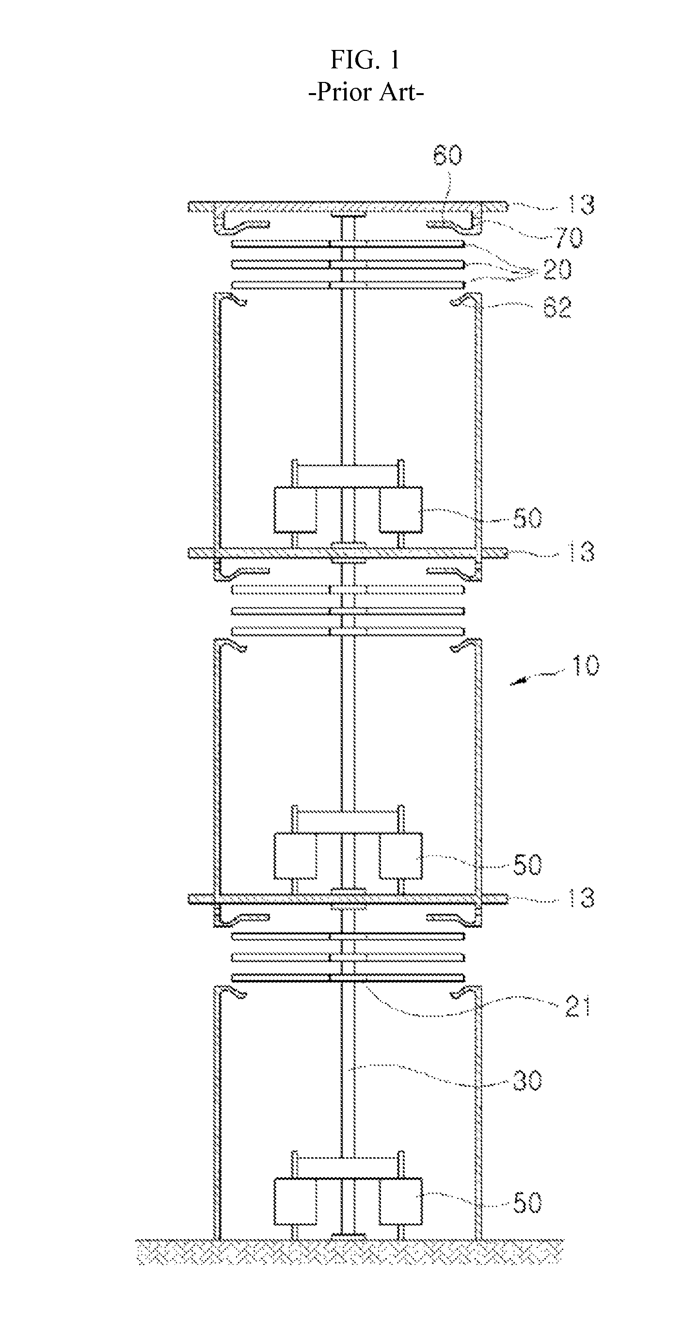
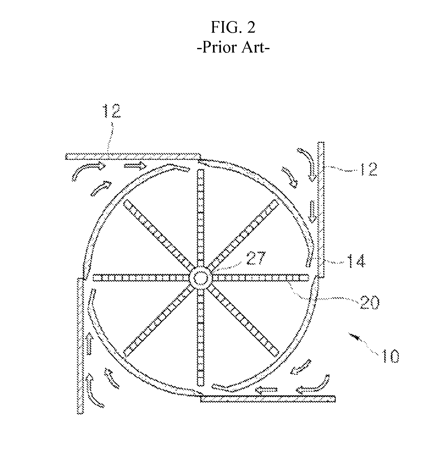
[0035]Prior to detailed description of the present invention, a wind power generating apparatus that has been filed and registered by the present applicant will be briefly described with reference to FIGS. 1 and 2.

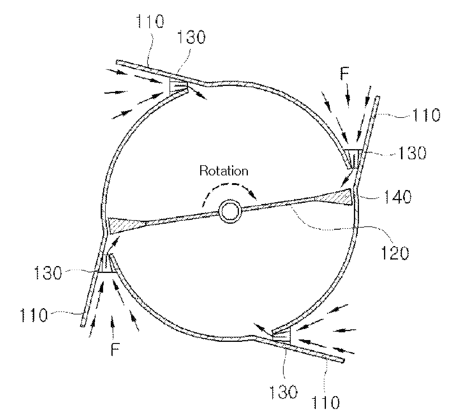
[0036]The shown wind power generating apparatus includes a generating tower 10 that has a generating space formed therein, a plurality of generating blades 20 that are axially installed along a center of the generating tower 10, wall surface through-holes 14 that penetrate an outer wall of the generating tower 10 and guide the inflow of wind toward the generating blade 20, a windshield plate (reference numeral ...


PUM


Abstract

Provided is a wind power generating apparatus including a generating tower that has a wall surface in which a plurality of through-holes for inflow of wind are formed, wind inlet walls that protrude outwardly from the respective through-holes so as to guide the inflow of wind, a generating blade that rotates by means of the wind introduced into the generating tower, a generator that generates electricity in conjunction with the rotation of the generating blade, a wind inlet port formed through the respective through-holes formed in the wall surface of the generating tower, and a wind contact member, which is connected to an end of the generating blade, which has a triangular pyramid shape with an open front surface so as to extend the area pressurized by the wind introduced through the wind inlet port, and which has a flow channel dividing member arranged across the open front surface.

Description

CROSS REFERENCE TO PRIOR APPLICATIONS[0001]This application is a National Stage Application of PCT International Patent Application No. PCT / KR2012 / 000389 filed on Jan. 17, 2012, under 35 U.S.C. §371, which claims priority to Korean Patent Application Nos. 10-2011-0009960 filed on Feb. 1, 2011 and 10-2011-0127753 filed on Dec. 1, 2011, which are all hereby incorporated by reference in their entirety.TECHNICAL FIELD[0002]The present invention relates to a wind power generating apparatus having a wind guide, and more particularly, to a wind power generating apparatus having a wind guide in which the wind guide is formed into a flared tunnel at a wind inlet port for the inflow of wind such that the wind guide is arranged at an inner surface of the wind inlet port, thereby improving the efficiency of wind power generation.BACKGROUND ART[0003]In general, wind power generating apparatuses produce electricity using the power of wind that is infinite in nature, and have long been developed a...

Claims


Application Information

Patent Timeline
Patent Type & Authority Patents(United States)
IPC IPC(8): F03D9/00F03D3/00F03D3/02F03D3/04H02K7/18
CPCH02K7/1807H02K7/183F03D3/005F03D3/02F03D3/04F03D3/0427Y02E10/74Y02E70/30F03D3/0454F03D9/25F05B2240/211
Inventor KO, YOUNG-EUN
Owner KO YOUNG EUN
Why Eureka
Try Eureka