
Method of calibrating a force balance

Active Publication Date: 2015-06-09
NASA
View PDF45 Cites 23 Cited by
  • Summary
  • Abstract
  • Description
  • Claims
  • Application Information

AI Technical Summary

Benefits of technology

The patent describes a system and method for calibrating force balances by changing accuracies while keeping the mass constant. This allows for the use of small test masses to generate large forces. Multiple forces can be applied without changing the mass, and dynamic forces can be applied by rotation or oscillating acceleration. The calibration can include measuring and adjusting balance deflections during post-processing stages. Overall, the invention enables accurate calibration of force balances even when using small test masses.

Problems solved by technology

Fully automated designs have been used to reduce the time involved in calibrating a balance; however, the new designs still have significant disadvantages.
These calibration systems are typically not portable, and must be installed at a fixed location.
In addition, the calibration system accuracy may be difficult to experimentally verify.
However, known force calibration systems suffer from various drawbacks.

Method used


Image

  • Method of calibrating a force balance
  • Method of calibrating a force balance
  • Method of calibrating a force balance

Examples


Embodiment Construction

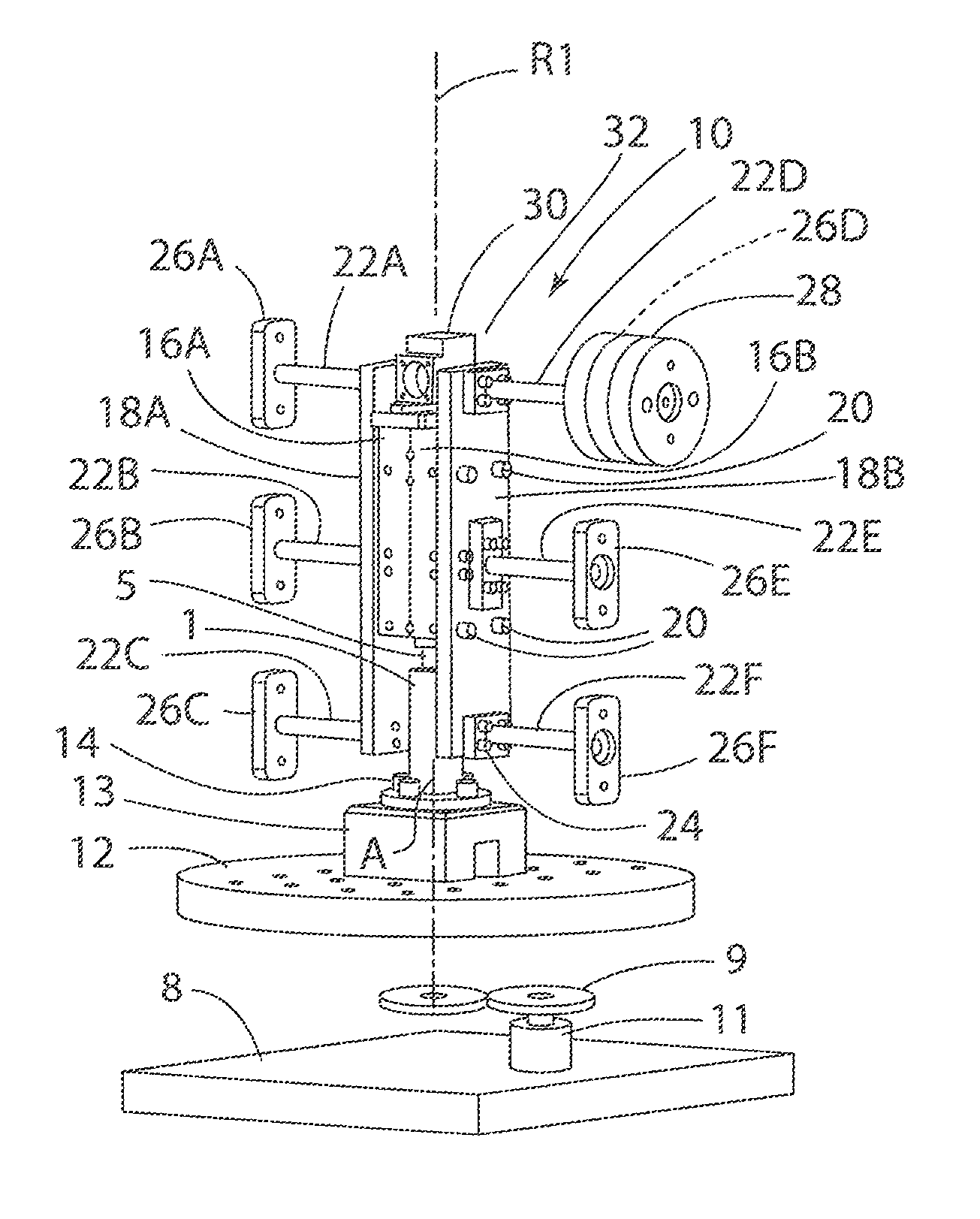
[0016]For purposes of description herein, the terms “upper,”“lower,”“right,”“left,”“rear,”“front,”“vertical,”“horizontal,” and derivatives thereof shall relate to the invention as oriented in FIGS. 3 and 4. However, it is to be understood that the invention may assume various alternative orientations, except where expressly specified to the contrary. It is also to be understood that the specific devices and processes illustrated in the attached drawings, and described in the following specification are simply exemplary embodiments of the inventive concepts defined in the appended claims. Hence, specific dimensions and other physical characteristics relating to the embodiments disclosed herein are not to be considered as limiting, unless the claims expressly state otherwise.

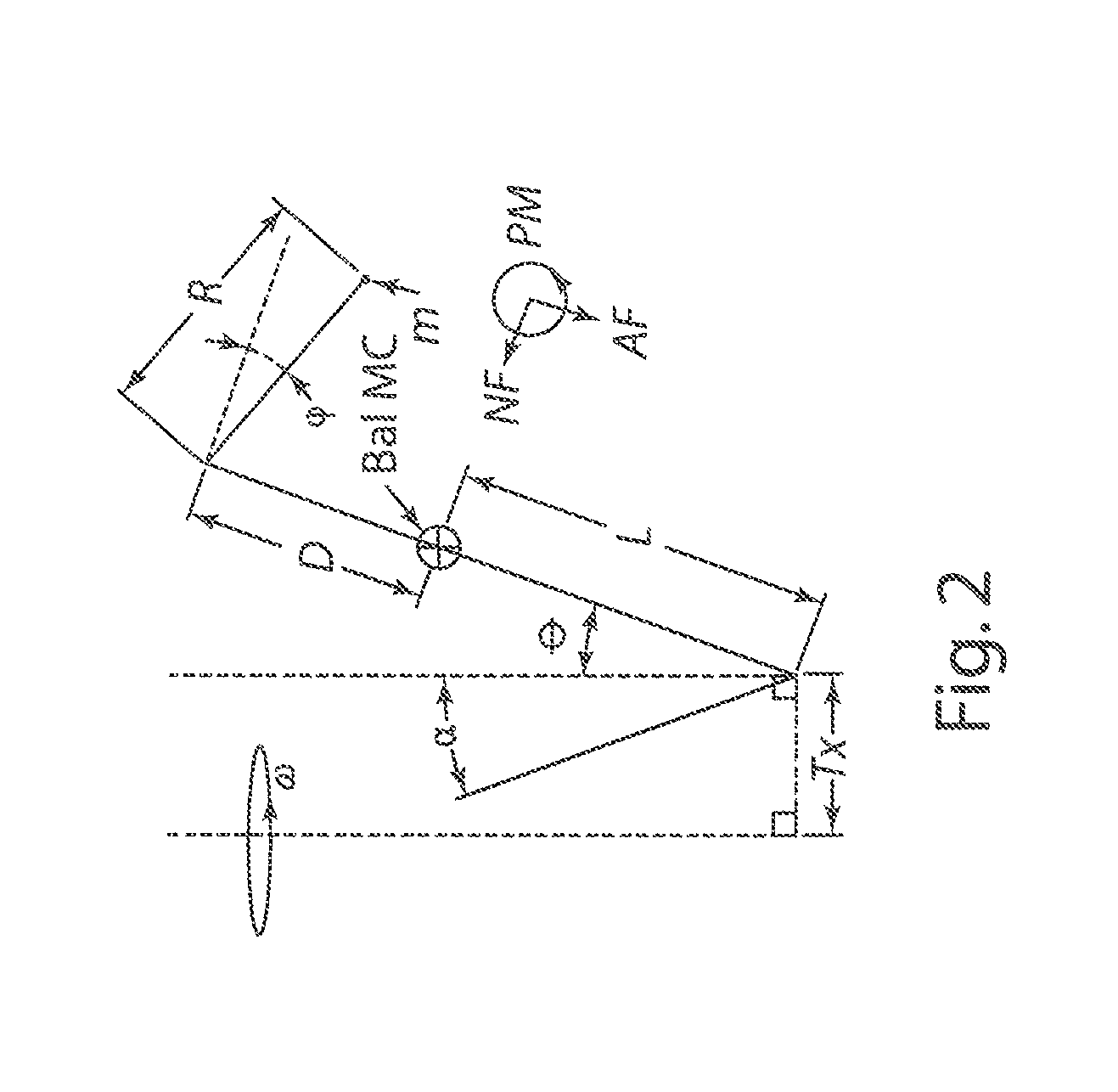
[0017]The following nomenclature is utilized herein:[0018]ω=angular velocity[0019]α=angle between the table rotational axis and earth's gravitational vector[0020]θ=angle between the axis of the balance and the tab...


PUM


Abstract

A calibration system and method utilizes acceleration of a mass to generate a force on the mass. An expected value of the force is calculated based on the magnitude and acceleration of the mass. A fixture is utilized to mount the mass to a force balance, and the force balance is calibrated to provide a reading consistent with the expected force determined for a given acceleration. The acceleration can be varied to provide different expected forces, and the force balance can be calibrated for different applied forces. The acceleration may result from linear acceleration of the mass or rotational movement of the mass.

Description

CROSS-REFERENCE TO RELATED PATENT APPLICATION(S)[0001]This patent application claims the benefit of and priority to U.S. Provisional Patent Application No. 61 / 642,613, filed on May 4, 2012, the contents of which are hereby incorporated by reference in their entirety.STATEMENT REGARDING FEDERALLY SPONSORED RESEARCH OR DEVELOPMENT[0002]The invention described herein was made in part by employees of the United States Government and may be manufactured and used by or for the Government of the United States of America for governmental purposes without the payment of any royalties thereon or therefore.FIELD OF THE INVENTION[0003]The present invention generally relates to the field of precision force measurement systems. In particular, the present invention relates to a system for calibrating high precision multi-axis load cells such as wind tunnel force balances. An example of a wind tunnel force balance is disclosed in U.S. Pat. No. 5,663,497 entitled “Six Component Wind Tunnel Balance,”...

Claims


Application Information

Patent Timeline
IPC IPC(8): G01L25/00G01P21/00G01L3/00G01G23/01
CPCG01L25/00G01P21/00G01M9/062
Inventor PARKER, PETER A.RHEW, RAY D.JOHNSON, THOMAS H.LANDMAN, DREW
Owner NASA
Features
  • Generate Ideas
  • Intellectual Property
  • Life Sciences
  • Materials
  • Tech Scout
  • Unparalleled Data Quality
  • Higher Quality Content
  • 60% Fewer Hallucinations
Learn More