Camera module

a camera module and camera technology, applied in the field of camera modules, can solve the problems of voluminous and limited accuracy in control and miniaturization of camera modules, and achieve the effect of miniaturizing the size of the camera modules

Active Publication Date: 2015-06-09
LG INNOTEK CO LTD
View PDF19 Cites 16 Cited by
  • Summary
  • Abstract
  • Description
  • Claims
  • Application Information

AI Technical Summary

Benefits of technology

[0030]The camera module according to exemplary embodiments of the present disclosure has an advantageous effect in that size of the camera module can be miniaturized by lifting and tilting a relatively light image sensor to implement an auto focusing function.
[0031]Another advantageous effect is that tilting of the image sensor can be controlled to compensate dispersion of focus at a remote isolated portion of the image sensor, in a case the camera module according the exemplary embodiments of the present disclosure is applied to a camera module using a conventional VCM as an auto focusing unit.

Problems solved by technology

A VCM (Voice Coil Motor) is commonly used to implement an autofocus function, but the VCM suffers from disadvantages in that it is voluminous and limited in accurate control and miniaturization of camera module.

Method used


Image

  • Camera module
  • Camera module
  • Camera module

Examples


Embodiment Construction

[0041]Now, the camera module according to exemplary embodiments of the present invention will be described in detail with reference to the accompanying drawings.

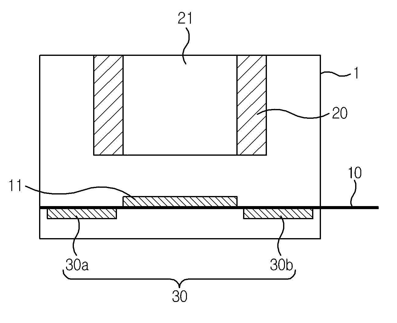
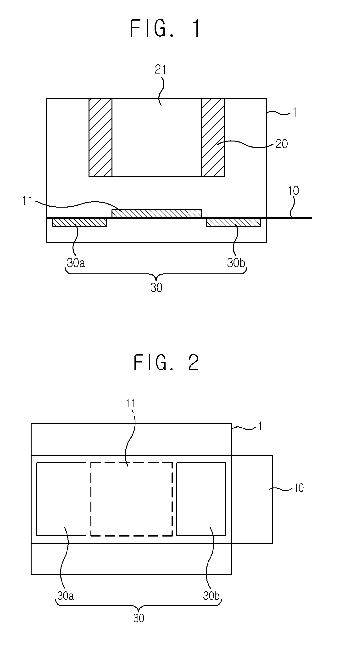
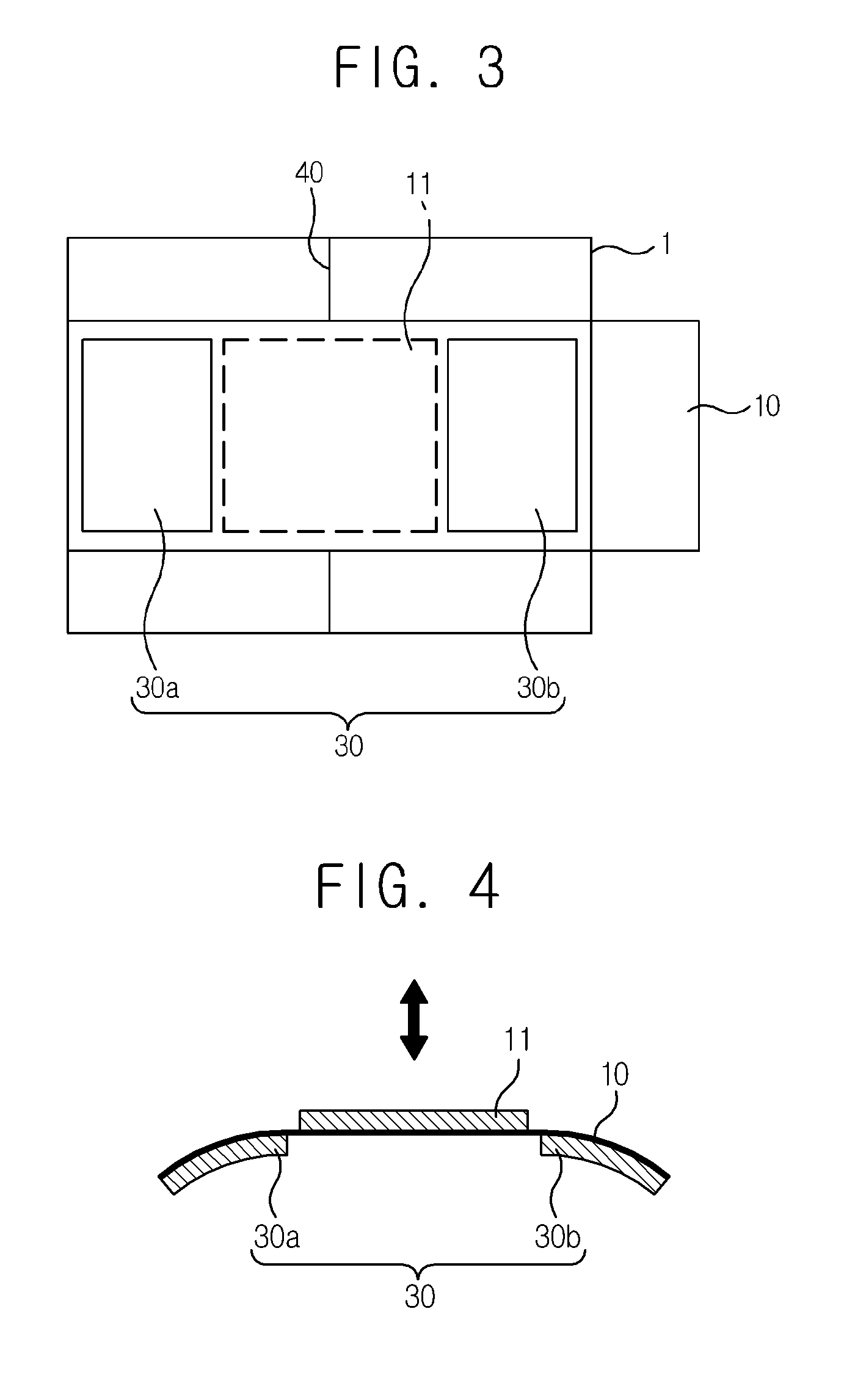
[0042]FIG. 1 is a schematic cross-sectional view illustrating a lateral surface of a camera module according to an exemplary embodiment of the present disclosure, FIG. 2 is a schematic view illustrating a bottom of the camera module of FIG. 1 according to a first exemplary embodiment of the present disclosure, FIG. 3 is a schematic view illustrating a bottom of the camera module of FIG. 1 according to a second exemplary embodiment of the present disclosure, FIG. 4 is a schematic view illustrating an operation of auto focusing function of an image sensor according to an exemplary embodiment of the present disclosure, FIG. 5 is a schematic view illustrating an operation of handshake compensation function of an image sensor according to an exemplary embodiment of the present disclosure, FIG. 6 is a schematic view illustrating a...


PUM


Abstract

A camera module according to an exemplary embodiment of the present disclosure includes a housing forming an exterior appearance of the camera module, a PCB (Printed Circuit Board) mounted with an image sensor where one end of which is fixed to the housing and the other end is exposed to an outside to be connected to other parts, a lens holder including at least one or more pieces of lenses and so arranged as to be spaced apart from the image sensor at a predetermined distance, and at least two actuators mounted at areas other than an image sensor-mounted area of the PCB, wherein a position of the image sensor is controlled in response to strains of the actuators.

Description

[0001]Pursuant to 35 U.S.C. §119 (a), this application claims the benefit of earlier filing date and right of priority to Korean Patent Application No. 10-2012-0028565, filed on Mar. 21, 2012, the contents of which are hereby incorporated by reference in their entirety.BACKGROUND OF THE DISCLOSURE[0002]1. Field of Endeavor[0003]The teachings in accordance with exemplary and non-limiting embodiments of this disclosure relate generally to a camera module.[0004]2. Background[0005]This section provides background information related to the present disclosure which is not necessarily prior art.[0006]Recently, small-sized camera modules are highly demanded in a variety of multimedia fields, such as tablet computers, camera phones, PDAs (Personal Digital Assistants), smart phones, and toys, and image input devices, such as monitoring cameras and information terminals of video tape recorders. Particularly, trends are to develop miniaturized camera modules for smart phones in response to inc...

Claims


Application Information

Patent Timeline
Patent Type & Authority Patents(United States)
IPC IPC(8): H04N5/225H04N5/232
CPCH04N5/2254H04N5/2253H04N5/2257H04N5/23212H04N5/2328H04N23/57H04N23/54H04N23/685G03B13/36
Inventor KIM, HACK HO
Owner LG INNOTEK CO LTD
Why Eureka
Try Eureka