Electrostatic suction type fluid discharge device, electrostatic suction type fluid discharge method, and plot patern formation method using the same
a technology of electrostatic suction and fluid discharge, which is applied in the direction of conductive pattern formation, printing, printed circuit manufacturing, etc., can solve the problems of increasing the electric field strength required, the reduction of the diameter of the nozzle hole is not compatible with etc., and achieves the reduction of the drive voltage and the precision of the landing position
- Summary
- Abstract
- Description
- Claims
- Application Information
AI Technical Summary
Benefits of technology
Problems solved by technology
Method used
Image
Examples
embodiment 1
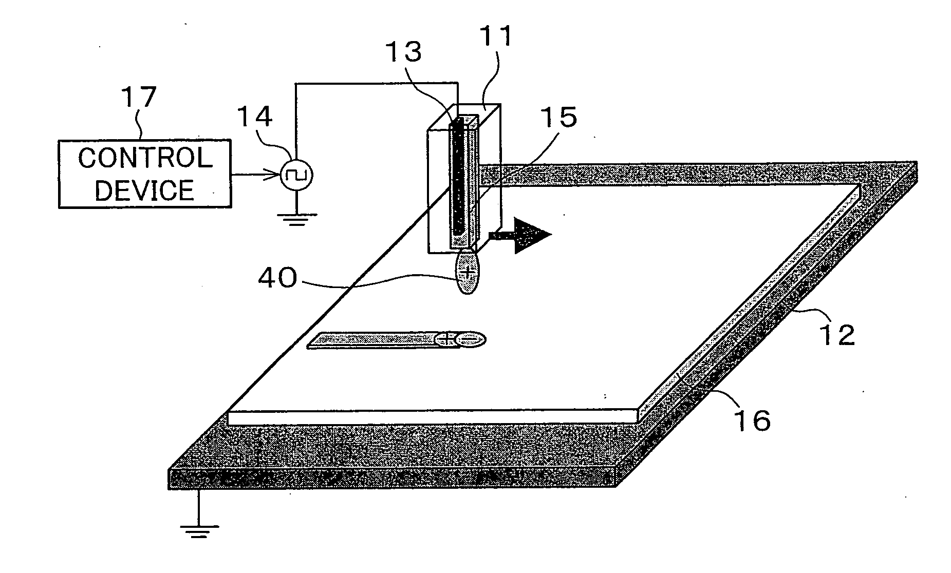
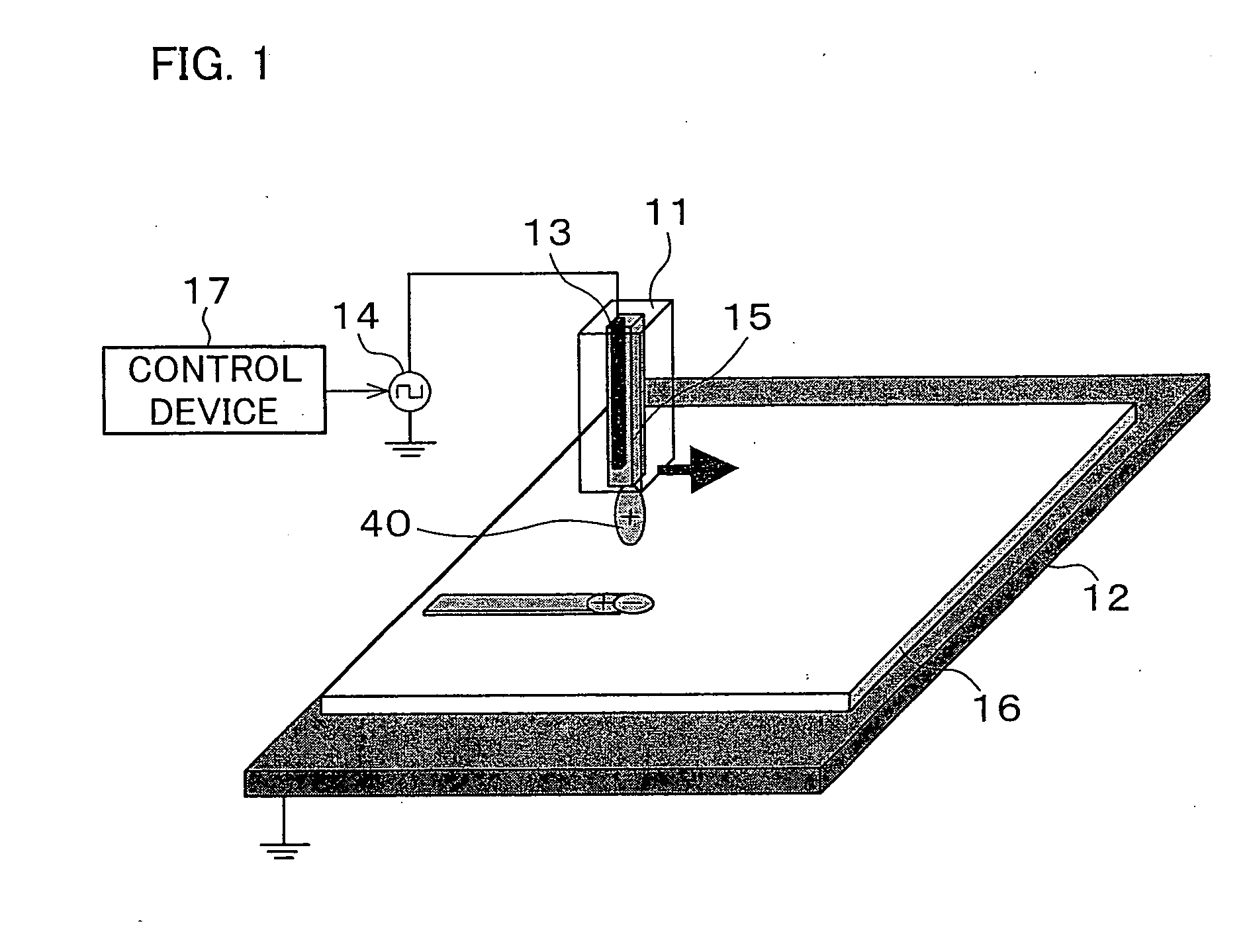
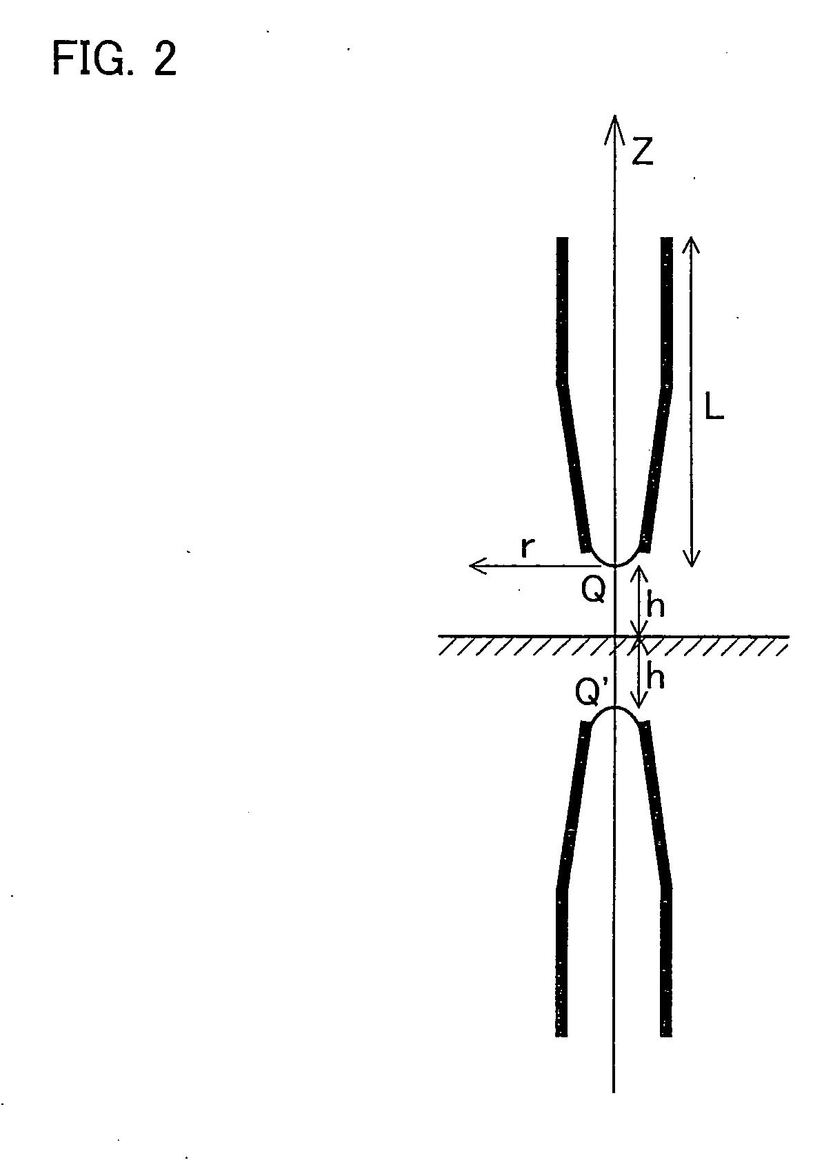
[0140] As described in the presupposed technology, the electrostatic suction type fluid discharge device is arranged such that, the reduction of the diameter of the nozzle hole and the reduction of the drive voltage are both achieved by causing the diameter (nozzle diameter) of the nozzle hole to fall in the range of φ0.01 to 25 μm.
[0141] An amount of discharged liquid, which is discharged from the nozzle, can be controlled by changing (i) the electric potential difference between the nozzle and a discharge target and (ii) the distance between the nozzle and the discharge target, i.e. the gap. Basically, the field strength at the tip of the nozzle is increased as the potential difference is increased, or as the gap is shortened. In this manner, an amount of discharged liquid is easily controlled.
[0142] However, the electrostatic suction type fluid discharge method is accompanied by the aforesaid problem of the charge-up of the substrate. That is, to discharge a liquid to an insula...
embodiment 2
[0174] The following will describe another embodiment of the present invention, in reference to figures.
[0175] FIGS. 14(a) and 14(b) are waveform charts showing the relationship between (i) the waveform of the bipolar pulse voltage which is the drive voltage applied to the drive electrode 13 of the nozzle 11 and (ii) the surface potential of the discharge material 15 at the tip of the nozzle 11. FIG. 14(a) shows a case where the nozzle 11 does not discharge the discharge material 15, whereas FIG. 14(b) shows a case where the nozzle 11 discharges the material 15. FIG. 15 illustrates how the electric charge supplied from the drive electrode 13 to the nozzle 11 is accumulated in the meniscus 40 at the tip of the nozzle 11. FIG. 16 illustrates how the discharge material 15 is discharged or not discharged from the nozzle 11, in a case where the drive voltage (drive voltage frequency) shown in FIG. 14(b) is used. FIG. 17 is a graph showing the relationship between the drive voltage frequ...
embodiment 3
[0188] The following will describe a further embodiment of the present invention in reference to figures.
[0189] The electrostatic suction type fluid discharge device of the present embodiment is arranged as shown in FIG. 20. That is, in the electrostatic suction type fluid discharge device of the present embodiment, the stage 12 is driven by a shifting device (shifting means) 21 so as to be moved. A control device (control means) 22 controls the direction, speed, and timing of the movement by the shifting device 21. The control device 22 also controls (i) the drive voltage supplied from the power source 14 to the drive electrode 13 of the nozzle 11, (ii) the drive voltage frequency, (iii) when the drive voltage is applied, and the like.
[0190]FIG. 21 is a graph showing the relationship between the scanning speed of the stage 12 and the width of the area where the droplets scatter on the insulating substrate 16, in the electrostatic suction type fluid discharge device of the present...
PUM
 Abstract
Description
Claims
Application Information
 - R&D
- Intellectual Property
- Life Sciences
- Materials
- Tech Scout
- Unparalleled Data Quality
- Higher Quality Content
- 60% Fewer Hallucinations
Browse by: Latest US Patents, China's latest patents, Technical Efficacy Thesaurus, Application Domain, Technology Topic, Popular Technical Reports.
© 2025 PatSnap. All rights reserved.Legal|Privacy policy|Modern Slavery Act Transparency Statement|Sitemap|About US| Contact US: help@patsnap.com


