Power supply system and electronic instrument

a power supply system and electronic instrument technology, applied in the direction of ac network voltage adjustment, transportation and packaging, dc source parallel operation, etc., can solve the problem of difficult to achieve the miniaturization of the instrument as a whole, and achieve the effect of reducing the burden on the battery and electric power system, and prolonging the battery li

Inactive Publication Date: 2010-06-17
SONY MOBILE COMM INC
View PDF17 Cites 20 Cited by
  • Summary
  • Abstract
  • Description
  • Claims
  • Application Information

AI Technical Summary

Benefits of technology

[0013]According to an embodiment of the present invention, by alleviating the burden on the battery and electric power system, longer operating life of the battery can be realized. In addition, since one single large-capacitance capacitor is shared by the plurality of loads, the size of the power supply system as well as electronic instrument can be miniaturized.

Problems solved by technology

However, since the capacitor with the capacitance as large as the order of several hundred millifarads (mF), which is necessary for the power assists, tends to have the size as large as 18 mm×15 mm even after seeking the smallest at present, it is difficult to achieve the miniaturization of an instrument as a whole, while mounting such capacitor onto each of the power supply units of plural components included in the instrument.

Method used


Image

  • Power supply system and electronic instrument
  • Power supply system and electronic instrument
  • Power supply system and electronic instrument

Examples


Embodiment Construction

[0022]Referring now to the drawings, preferable embodiments of the present invention will be detailed hereinbelow.

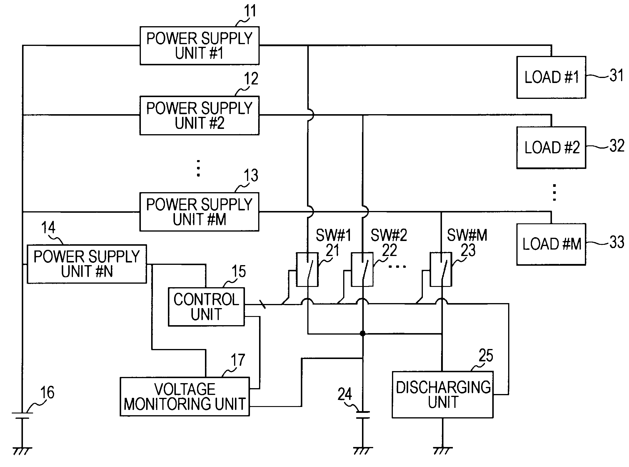
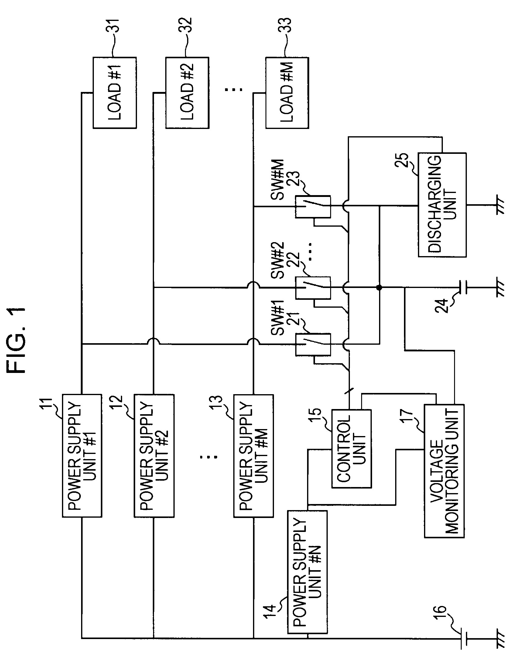
[0023]FIG. 1 is a schematic block diagram generally illustrating the configuration of a power supply system, which is configured to supply electric powers to a plurality of loads (#1 to #M) 31 to 33, according to an embodiment of the invention.

[0024]The power supply system is provided including a first plurality of power supply units (#1 to #N) 11 to 14, a voltage monitoring unit 17, a second plurality of switches (SW #1 to SW #M) 21 to 23 as switching means, a large-capacitance capacitor 24, and a discharge unit 25. Among these units and elements, the voltage monitoring unit 17, the plural switches (SW #1 to SW #M) 21 to 23 as switching means, the large-capacitance capacitor 24, and the discharge unit 25 altogether serves as an auxiliary power supply for the power supply system.

[0025]On receiving an output voltage supplied by a battery 16, plural power supply units, 11 ...


PUM


Abstract

A power supply system is disclosed, including a first plurality of power supply units configured to supply working voltages from a battery to a second plurality of loads, a large-capacitance capacitor configured to charge electric charges from the battery, a third plurality of switching means for connecting the large-capacitance capacitor to the second plurality of loads selectively, control means for switching the third plurality of switching means corresponding to the load presently driven, and discharge means, in a case where the output voltage of the large-capacitance capacitor is higher than the operating voltage of the second load when the capacitor is switched from a first load to a second load, for discharging the charges stored in the capacitor according to the monitoring result by a voltage monitoring means so that the voltage of the capacitor decreases to the operating voltage.

Description

BACKGROUND OF THE INVENTION[0001]1. Field of the Invention[0002]The invention relates to power supply systems and electronic instruments. More particularly, the invention relates to a power supply system for supplying power to plural loads and an electronic instrument including the power supply system.[0003]2. Description of the Related Art[0004]In order to extend the operating time of batteries and to reduce the size and weight of mobile communication terminals operational in the system such as the time division multiple access (TDMA), time division duplication (TDD), and so forth, there has been proposed the technology of reducing the burden on the battery and resulting in longer battery life by supplying power from an electric double-layer capacitor to a power amplifier (see, Japanese Unexamined Patent Application Publication No. 2004-297753).[0005]In addition, in the case where power is supplied to a camera flash from an electric double-layer capacitor, there has been proposed t...

Claims


Application Information

Patent Timeline
Patent Type & Authority Applications(United States)
IPC IPC(8): H02J1/00
CPCH02J1/102H02J7/345H02J7/0065H02J2207/20
Inventor TANIUCHI, HIROTADA
Owner SONY MOBILE COMM INC
Why Eureka
Try Eureka