Device and method for removing material from a hollow anatomical structure

a hollow anatomical structure and material technology, applied in medical science, surgery, diagnostics, etc., can solve the problem of small clot remaining in the vessel

Active Publication Date: 2015-06-16
ANGIODYNAMICS INC
View PDF50 Cites 10 Cited by
  • Summary
  • Abstract
  • Description
  • Claims
  • Application Information

AI Technical Summary

Benefits of technology

[0005]The device includes a macerator element near the distal end of the hollow shaft. The macerator element may be attached to the distal end of the drive shaft. The macerator element may be comprised of an auger element, rotating element, shearing member coaxially disposed and freely rotatable within an outer tubular extension, a rotating wire, or any combination of these various elements. The macerator element rotates along the central axis of the device to aid in mechanically removing, dissolving, disrupting, liquefying, or breaking down clot material from within a hollow anatomical structure. The rotations per minute and means for removing the clot material may change depending on the embodiment of macerator element being used. The device may include an aspiration or vacuum element to aid in removal of clot material. The device may be used in combination with a distal protection element, such as an expandable filter or inflatable balloon member.

Problems solved by technology

This manner of treatment may result in small pieces of clot remaining in the vessel after treatment, commonly attached to the vessel wall.
Problems with known methods of clot removal is it's a common requirement for the patient to remain overnight in the hospital or the treatment may not completely remove the clot from the vessel.

Method used


Image

  • Device and method for removing material from a hollow anatomical structure
  • Device and method for removing material from a hollow anatomical structure
  • Device and method for removing material from a hollow anatomical structure

Examples


Embodiment Construction

[0031]The present invention can be understood more readily by reference to the following detailed description and the examples included therein and to the figures and their previous and following description. The drawings, which are not necessarily to scale, depict selected preferred embodiments and are not intended to limit the scope of the invention. The detailed description illustrates by way of example, not by way of limitation, the principles of the invention.

[0032]The skilled artisan will readily appreciate that the devices and methods described herein are merely exemplary and that variations can be made without departing from the spirit and scope of the invention. It is also to be understood that the terminology used herein is for the purpose of describing particular embodiments only and is not intended to be limiting.

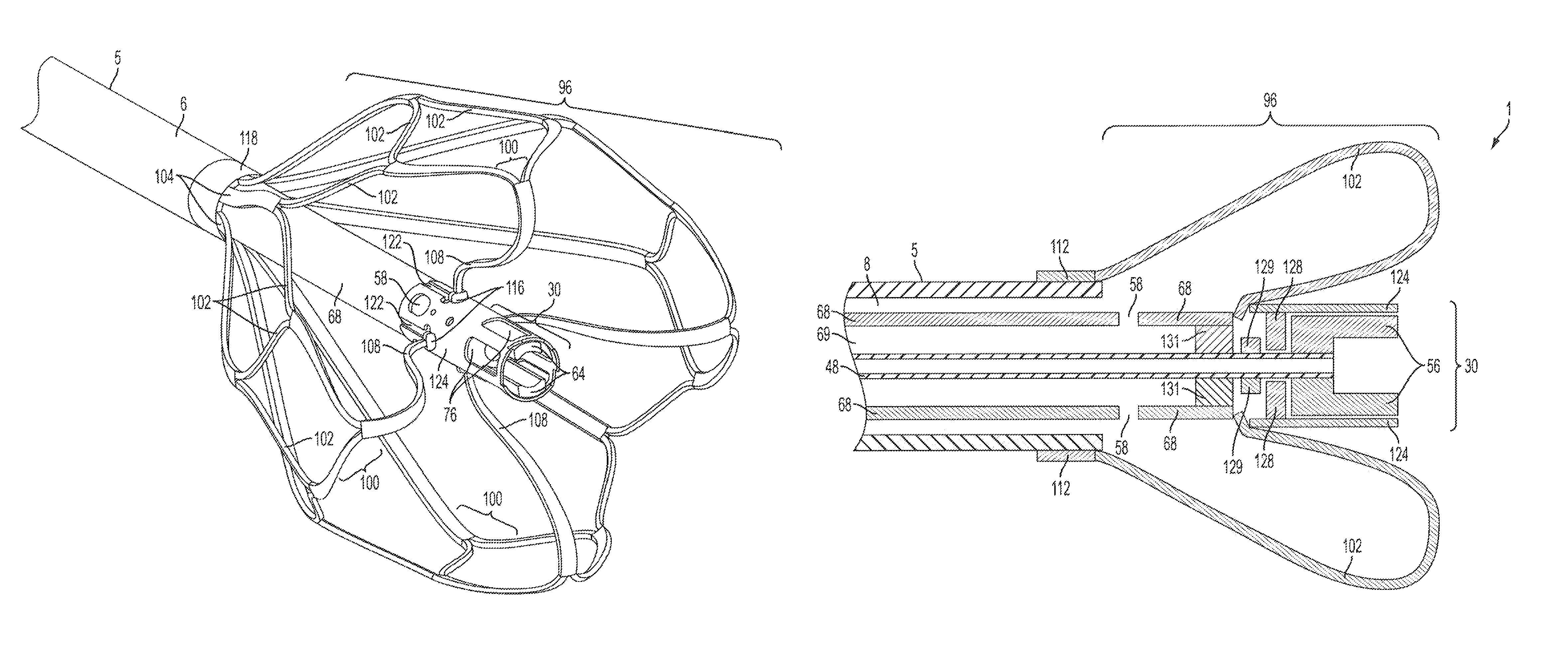
[0033]As used herein, the term “proximal” denotes the direction closer to the operator and the term “distal” denotes the direction closer to (inserted into) the...


PUM


Abstract

A medical device for removing a material from a hollow anatomical structure is provided. The device may include a shaft member. The device may include an expandable centering element near the distal end of the device. The device may include a macerator element either attached to the shaft or independent and freely moveable from the shaft. Alternatively, the device may include a rotating wire attached to the macerator element. The device may include an aspiration lumen in for removal of material. The device may include a drive shaft attached to a motor and used to rotate the macerator element. The device may be used in combination with a distal occlusion element, which may be either a radially expandable filter or balloon member.

Description

CROSS REFERENCE TO RELATED APPLICATIONS[0001]This application claims priority under 35 U.S.C. §119(e) to U.S. Provisional Application No. 61 / 452,838, filed Mar. 15, 2011, U.S. Provisional Application No. 61 / 521,494, filed Aug. 9, 2011, and U.S. Provisional Application No. 61 / 585,348, filed Jan. 1, 2012, all of which are incorporated herein by reference.BACKGROUND[0002]Common types of treatment for removal of thrombus include fluid delivery, such as a lytic or other blood thinning medication. For example, a doctor may deliver a desired drug, such as lytic, to the treatment site adjacent to the clot in order to break down the clot matter. This manner of treatment may result in small pieces of clot remaining in the vessel after treatment, commonly attached to the vessel wall. Problems with known methods of clot removal is it's a common requirement for the patient to remain overnight in the hospital or the treatment may not completely remove the clot from the vessel. An object of this i...

Claims


Application Information

Patent Timeline
Patent Type & Authority Patents(United States)
IPC IPC(8): A61B17/22A61B17/221A61B17/3207A61B19/00
CPCA61B17/221A61B17/320758A61B2017/22038A61B2017/22067A61B2017/22068A61B2017/2212A61B2017/2215A61B2017/320733A61B2017/320775A61B2019/481A61B2217/005A61B2090/08021A61B2017/00685A61B17/320725A61B2017/320716
Inventor CARTIER, WILLIAM A.HAMILTON, JR., WILLIAM C.MITCHELL, JAMES J.LAGOE, DANIEL T.
Owner ANGIODYNAMICS INC
Why Eureka
Try Eureka