Flotation machine

a technology of flotting machine and flotting shaft, which is applied in the direction of mixing, rotary stirring mixer, transportation and packaging, etc., can solve the problems of reducing large space utilization in terms of height required by the transmission structure, and v-belt drive causing high internal stresses in the support structure, so as to improve the efficiency of power transmission and avoid transmission losses. , the effect of high torqu

Active Publication Date: 2015-06-16
METSO OUTOTEC (FINLAND) OY
View PDF8 Cites 6 Cited by
  • Summary
  • Abstract
  • Description
  • Claims
  • Application Information

AI Technical Summary

Benefits of technology

[0012]An advantage of the invention is that, as no gear system is needed, the direct drive of the drive shaft by the permanent magnet motor improves the efficiency of the power transmission, whereby losses due to transmission are omitted. By the permanent magnet motor, it is possible to provide a smooth start-up with a high torque and the adjustment of its rotational velocity is simple to arrange. The permanent magnet motor can be rendered flat, small-size and light-weight, whereby its space requirement is small and the supporting structures can be dimensioned to be lighter than before. The abrasive dust emitted from the flotation process does not damage the permanent magnet motor. A further advantage is that the bearing of the rotor axis of the permanent magnet motor and the bearing of the drive shaft can be integrated; in other words, the same bearings can support both the rotor axis of the permanent magnet and the drive shaft and receive the loads coming from the mixing. Air supply is easy to arrange using the hollow rotor axis.
[0013]The said fixed connection between the rotor axis and the drive shaft can be implemented, firstly, so that the lower end of the rotor axis is attached directly to the upper end of the drive shaft. In an embodiment of the flotation machine, the upper end of the drive shaft comprises a first attachment flange and the lower end of the rotor axis of the electric motor comprises a second attachment flange, which is adapted to be attached to the first attachment flange by a bolted joint.
[0014]On the other hand, the fixed connection can be implemented so that the rotor axis and the drive shaft form one continuous part, which is made of metal by casting, for example.
[0015]In an embodiment of the flotation machine, the permanent magnet motor is supported by a separate supporting framework, which is on top of the flotation cell.
[0016]In an embodiment of the flotation machine, the permanent magnet motor includes a stator, which is attached to the said framework above the flotation cell, and a rotor, the periphery of which comprises a number of permanent magnets, the rotor being fixedly connected to the said vertical rotor axis. The rotor axis is fitted with a bearing to rotate with respect to the stator, preferably by an upper bearing located above the rotor and preferably by a lower bearing located below the rotor, which bearings at the same time constitute the bearing of the drive shaft, which receives the loads caused by air distribution and mixing. Fitting the drive shaft with the bearing of the permanent magnet motor eliminates the need of a separate bearing unit. The upper and the lower bearing can also be located on the same side of the rotor, i.e., each one of them can either be located above or below the rotor and also outside the actual stator, i.e., when viewed in the direction of the rotor axis, above or below the stator.
[0017]In an embodiment of the flotation machine, the rotor axis comprises a second hollow interior, which together with the hollow interior of the drive shaft forms a flow channel for conducting flotation air to the rotor part. Air is simply fed from the end of the rotor axis of the electric motor into its hollow interior, through which it flows to the hollow interior of the drive shaft and further out of the air distribution holes of the rotor part of the mixer and into the slurry.

Problems solved by technology

A problem with the prior art is that the belt drive or gear box reduces the efficiency of the power transmission.
A further problem is the large space utilization in terms of height required by the transmission structure.
The V-belt drive also induces high internal stresses in the support structures.
There is a further problem that the present combination of the electric motor and V-belt drive or the gear box and bearing unit has a complex structure and it contains many parts that are susceptible to wearing and failure, reducing the reliability and causing a repeated need of maintenance.
The abrasive dust emitted from the flotation process causes wearing of the V belt and the V-belt drive pulleys.
Furthermore, the operation and transmission equipment is heavy and it requires a sturdy supporting structure, which incurs costs.
The air supply into the hollow drive shaft is difficult to arrange.

Method used


Image

  • Flotation machine
  • Flotation machine
  • Flotation machine

Examples


Embodiment Construction

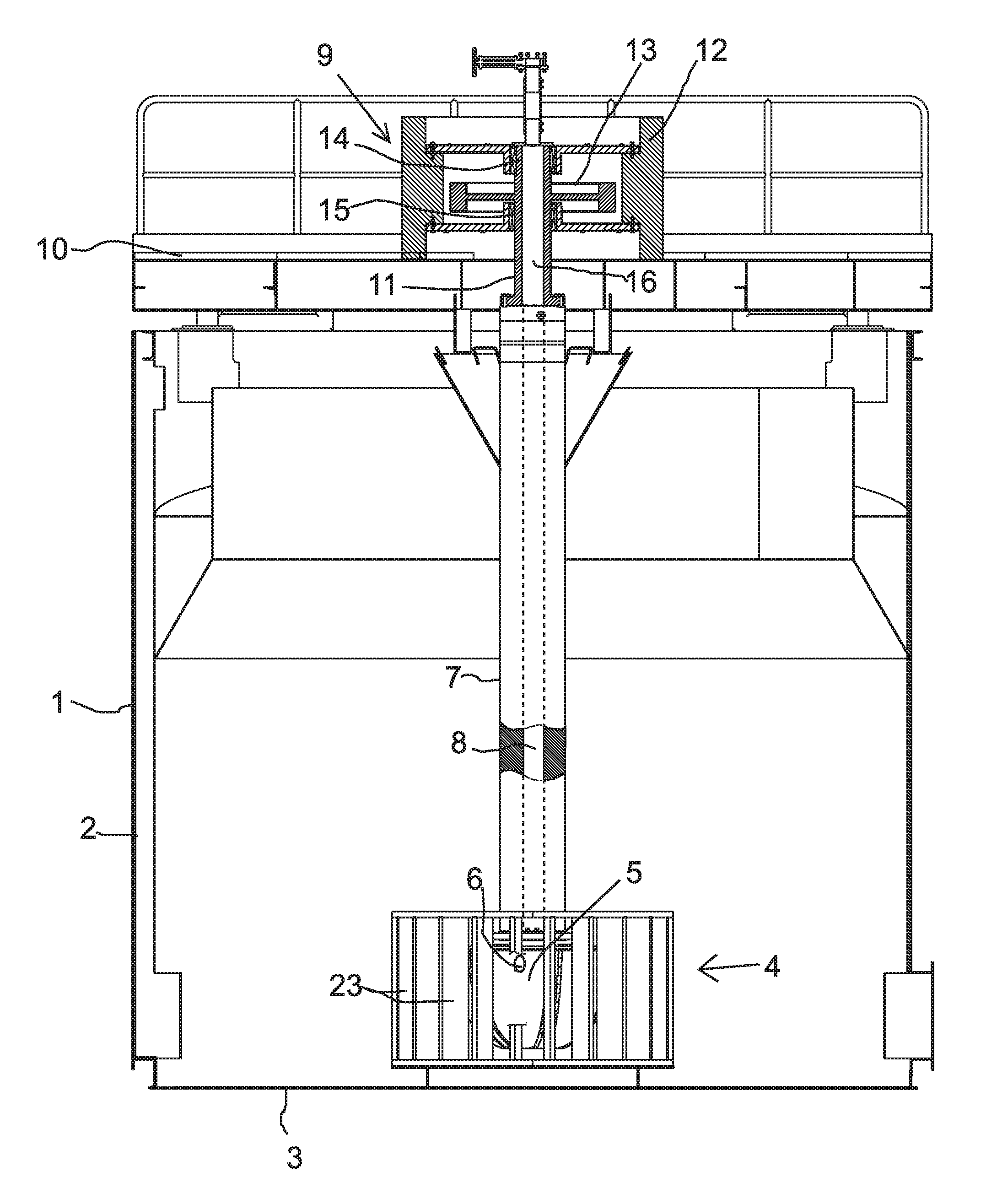
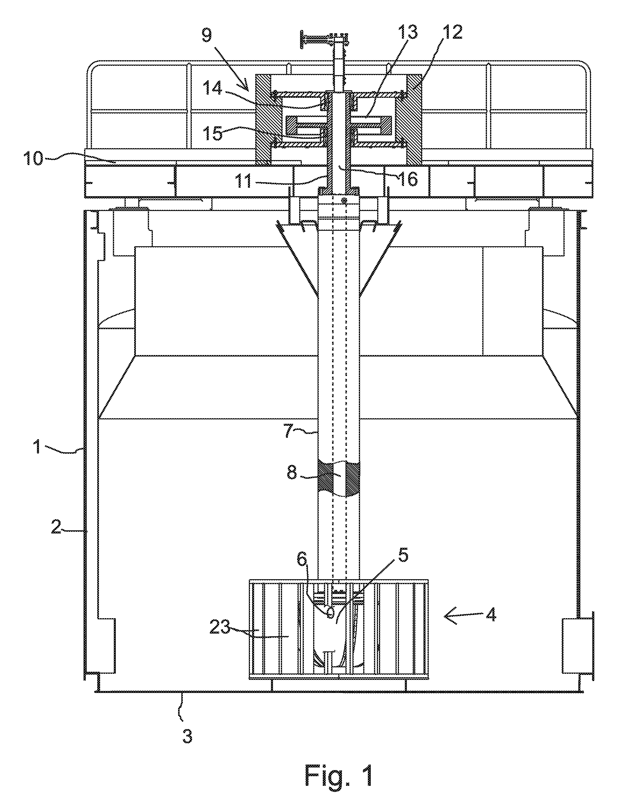
[0025]FIG. 1 shows a flotation machine for floating hydrophobic particles from aqueous slurry that contains these particles. In this example, the flotation machine includes an upwards-open (an upwards-closed model is also possible) flotation cell 1, which comprises a vertical side wall 2 and a bottom 3. The upwards-closed cell would also include a cover, which is not shown in the figure. An air distribution and mixing device 4 is arranged at the vertical centre line of the cell. Its purpose is to mix the slurry and, at the same time, distribute air into the slurry, so that air bubbles are formed, which rise and form froth in the upper part of the cell to exit as an overflow. The air distribution and mixing device includes a rotor part 5 that comprises air distribution apertures 6. Additionally, the air distribution and mixing device 4 includes a stationary stator part 23, which in this example is supported by the bottom 3 of the flotation cell. The support can also be arranged in an...


PUM

PropertyMeasurementUnit
hydrophobicaaaaaaaaaa
distanceaaaaaaaaaa
speedaaaaaaaaaa

Abstract

An air distribution and mixing device is arranged in the vicinity of the bottom of a flotation cell for distributing air to the slurry for forming froth and mixing the slurry in the flotation cell. A rotor part of the air distribution and mixing device has air distribution apertures and is attached to the lower end of a drive shaft extending vertically in the flotation cell. The drive shaft has a hollow interior, which constitutes a flow channel for conducting flotation air to the air distribution holes of the rotor part. An electric motor for rotating the drive shaft is supported by a separate supporting framework, which is on top of the flotation cell. The electric motor is a permanent magnet motor having a vertical rotor shaft, the lower end of which is in permanent contact directly with the upper end of the drive shaft.

Description

[0001]This is a national stage application filed under 35 USC 371 based on International Application No. PCT / FI2011 / 050161 filed Feb. 22, 2011, and claims priority under 35 USC 119 of Finnish Patent Application No. 20105170 filed Feb. 23, 2010.FIELD OF THE INVENTION[0002]The invention relates to the flotation machine defined in the preamble of claim 1.BACKGROUND OF THE INVENTION[0003]Flotation machines are known from before, e.g., from patent specifications FI 78628 B, FI 115612 B, WO 93 / 14876 for floating hydrophobic particles from aqueous slurry that contains these particles. Typically, the flotation machine includes a flotation cell, which comprises a vertical side wall and a bottom and, possibly, a cover. The flotation machine comprises one or more air distribution and mixing devices, which are arranged in the middle part of the cell for distributing air to the slurry to form froth an to mix the slurry in the flotation cell. The middle part of the cell refers to the location ess...

Claims


Application Information

Patent Timeline
Patent Type & Authority Patents(United States)
IPC IPC(8): B03D1/16B01F3/04B01F13/08B03D1/14B03D1/20C02F1/24B01F27/80B01F23/233B01F33/45
CPCB01F3/04539B03D1/16B01F3/04617B01F13/0827B01F13/0836C02F1/24B03D1/1412B03D1/20B01F2003/04546B01F2003/04652B01F2003/04687C02F2201/002B01F23/23311B01F23/23342B01F23/2331B01F23/23354B01F23/23364B01F33/4531B01F33/453B03D1/14B01F27/80
Inventor PELTOLA, ALEKSIRINNE, ANTTI
Owner METSO OUTOTEC (FINLAND) OY
Why Eureka
Try Eureka