Axial turbomachine having an axially displaceable guide-blade carrier

a technology of stator blades and axial turbomachines, which is applied in the direction of machines/engines, reaction engines, liquid fuel engines, etc., can solve the problems of the blade tips of the rotor blades brushing against the casing, and achieve the effects of high thermal efficiency, simple, reliable and accura

Inactive Publication Date: 2015-06-16
SIEMENS AG
View PDF15 Cites 3 Cited by
  • Summary
  • Abstract
  • Description
  • Claims
  • Application Information

AI Technical Summary

Benefits of technology

[0007]It is the object of the invention to create an axial turbomachine with high thermal efficiency, the device for radial gap setting of which is comparatively simple, reliable and accurate.
[0012]The fixing ring, on its side facing the adjusting ring, has a first sawtooth profile and the adjusting ring, on its side facing the fixing ring, preferably has a second sawtooth profile, wherein the sawtooth profiles engage with each other and can slide on each other in such a way that if the adjusting ring is axially rotated the stator blade carrier is axially displaced. Induced as a result of the sawtooth profiles of the two rings, an axially variable dimension is created between the casing step and the stator blade carrier step. As a result, by operating the adjusting ring the stator blade carrier can be axially displaced.
[0014]The adjusting ring is preferably supported on the fixing ring by a rolling bearing which is provided between the sawtooth profiles. The rotational axes of the rolling bearings lie in the radial direction of the turbomachine. As a result of the rolling bearings, rubbing and wear on the sawtooth profiles during operation of the adjusting ring are minimized, as a result of which the adjusting ring and the fixing ring have a long service life.
[0015]Provision is preferably made in the annular slot for a pretensioning device which is supported on the casing and acts on the stator blade carrier step in counteraction to the adjusting ring so that by means of the pretensioning device the stator blade carrier step is constantly pressed onto the adjusting ring. Consequently, a restoring movement of the stator blade carrier, induced as a result of a corresponding restoring force, can be brought about by the pretensioning device, as a result of which the stator blade carrier can be reliably moved axially back and forth by the adjusting ring. The pretensioning device is preferably a helical spring.

Problems solved by technology

Until the components of the casing have correspondingly warmed through and have thermally expanded to a larger diameter after startup, there is the risk of the rotor blades brushing against the casing by their blade tips.

Method used


Image

  • Axial turbomachine having an axially displaceable guide-blade carrier
  • Axial turbomachine having an axially displaceable guide-blade carrier
  • Axial turbomachine having an axially displaceable guide-blade carrier

Examples


Embodiment Construction

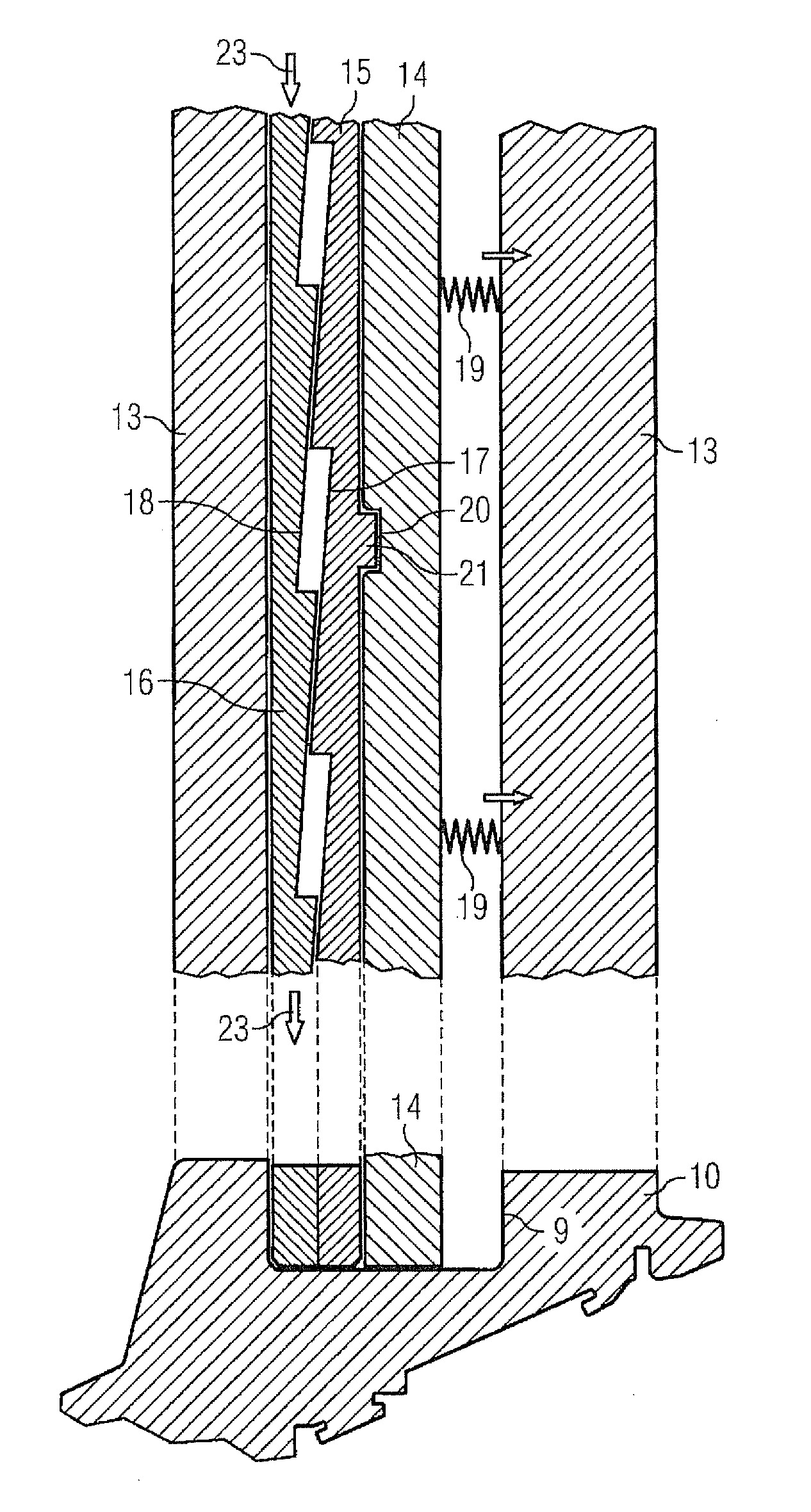
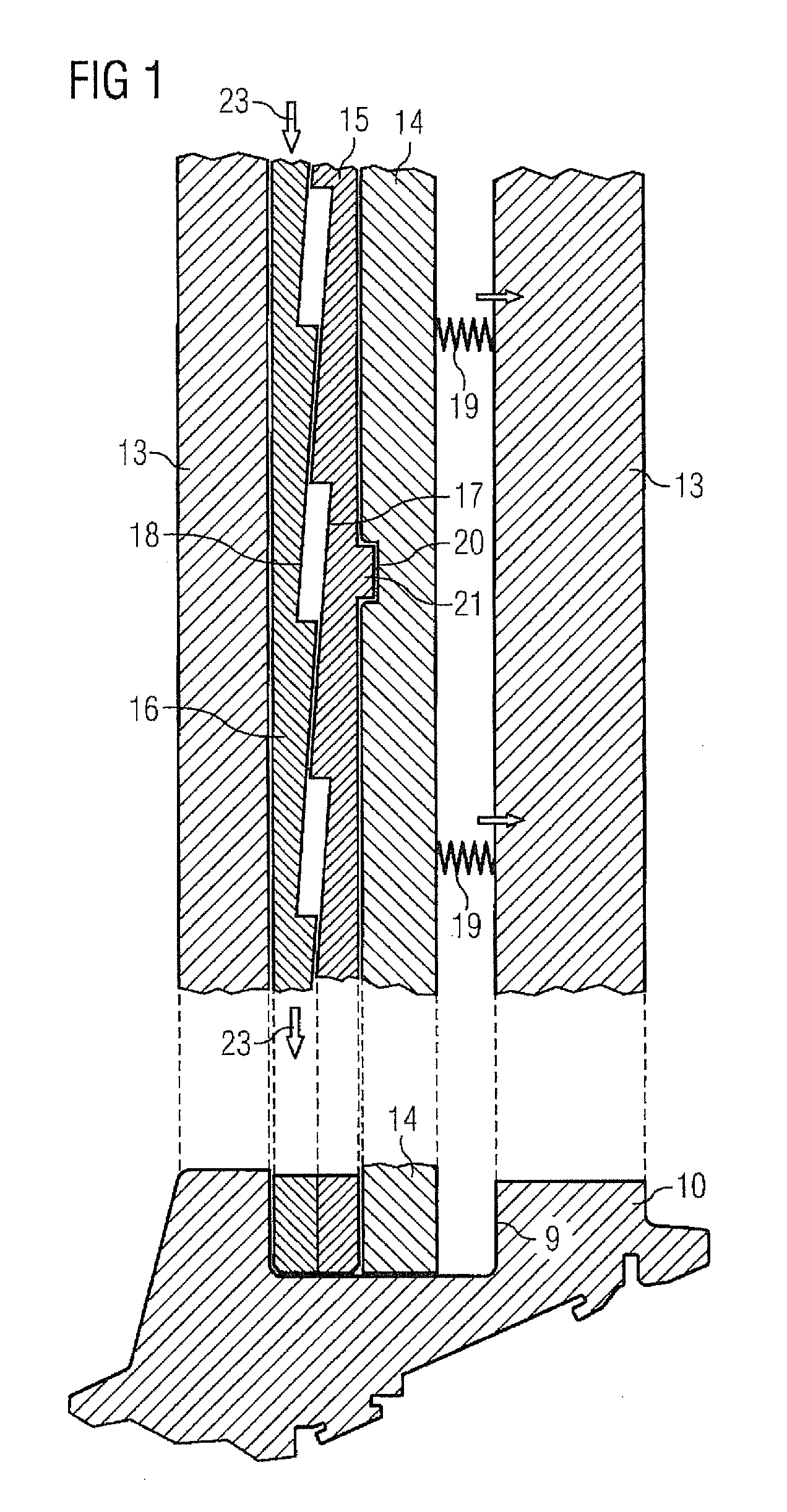
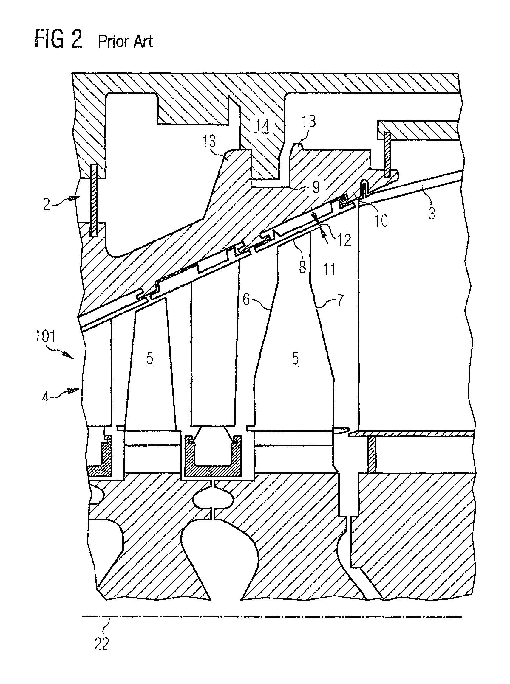
[0020]In FIG. 2, a conventional axial turbomachine 101 is shown. The axial turbomachine 101 has a casing 2 with an inner side 3 by which a main flow passage 4 is defined. Arranged in the main flow passage 4 is a rotor blade ring which is formed from a multiplicity of rotor blades 5 which are arranged in a distributed manner around the circumference. Each of the rotor blades 5 has a leading edge 6 upstream and a trailing edge 7 downstream. Radially towards the outside, the rotor blade 5 is delimited by a blade tip 8. The main flow passage 4 is exposed to throughflow from left to right in the main flow direction in FIG. 2, wherein the main flow passage 4 widens in the main flow direction. As a result, the inner side 3 of the casing 2 is arranged in an inclined manner to the axis 22 of the axial turbomachine 101.

[0021]Radially in the region of the blade tip 8, provision is made in the casing 2 for a stator blade carrier 10. Facing the axis 22 of the axial turbomachine 101, the stator b...


PUM


Abstract

An axial turbomachine including a rotor-blade cascade is provided. The turbomachine includes a casing in which the cascade is installed and a guide-blade carrier which encloses the cascade and is integrated into the inner side of the housing. The guide-blade carrier is arranged immediately adjacently to the blade tips faulting a radial gap, wherein the guide-blade carrier is mounted in the housing, such that it may be displaced parallel to the axis of the axial turbomachine, and includes an adjusting ring which is supported on contact surfaces on the housing and guide-blade carrier and may be rotated about the axis, wherein the contact surfaces of the adjusting ring and of the housing and / or of the guide-blade carrier are set with respect to a plane perpendicular to the axis, so that, when the adjusting ring is rotated about the axis, the guide-blade carrier is displaced axially by the adjusting ring.

Description

CROSS REFERENCE TO RELATED APPLICATIONS[0001]This application is the US National Stage of International Application No. PCT / EP2010 / 053663, filed Mar. 22, 2010 and claims the benefit thereof. The International Application claims the benefits of European Patent Office application No. 09004409.0 EP filed Mar. 26, 2009. All of the applications are incorporated by reference herein in their entirety.FIELD OF INVENTION[0002]The invention refers to an axial turbomachine with an axially displaceable stator blade carrier.BACKGROUND OF INVENTION[0003]In an axial turbomachine, radial gaps between rotor blades and the casing lead to significant losses in thermal efficiency. In order to achieve an efficiency which is as high as possible, it is desirable to keep the radial gaps as small as possible at all operating points of the axial turbomachine. The axial turbomachine is a gas turbine, for example. During start-up and shutdown of the gas turbine, the radial gaps vary over time. Furthermore, the...

Claims


Application Information

Patent Timeline
Patent Type & Authority Patents(United States)
IPC IPC(8): F01D1/04F01D11/22
CPCF01D11/22F05D2230/64F05D2250/314F05D2260/50F05D2230/644
Inventor BENKLER, FRANCOISBOTTCHER, ANDREASKAHLSTORF, UWEMATTHIAS, TORSTENMINNINGER, DIETERSCHNEIDER, OLIVERSCHRODER, PETERVEITSMAN, VYACHESLAV
Owner SIEMENS AG
Why Eureka
Try Eureka