Check patentability & draft patents in minutes with Patsnap Eureka AI!

Power supply device system, switching power supply device, control parameter generation device, and program

a power supply device and switching power supply technology, applied in the direction of power conversion systems, ac-ac conversion, conversion with intermediate conversion to dc, etc., can solve the problem of increasing design and manufacture costs, and achieve the effect of low cos

Inactive Publication Date: 2015-06-16
MINEBEAMITSUMI INC
View PDF7 Cites 0 Cited by
  • Summary
  • Abstract
  • Description
  • Claims
  • Application Information

AI Technical Summary

Benefits of technology

This solution allows for cost-effective changes in power supply device features and specifications without modifying circuit configurations or element constants, enhancing adaptability and reducing design and manufacturing costs.

Problems solved by technology

However, there is a drawback such that costs of design and manufacture will increase caused by increase in the number of features and types of LED load or increase in the number of specifications and types of lighting device equipped with LED load and power supply thereof.

Method used


Image

  • Power supply device system, switching power supply device, control parameter generation device, and program
  • Power supply device system, switching power supply device, control parameter generation device, and program
  • Power supply device system, switching power supply device, control parameter generation device, and program

Examples


embodiment

Effect of Embodiment

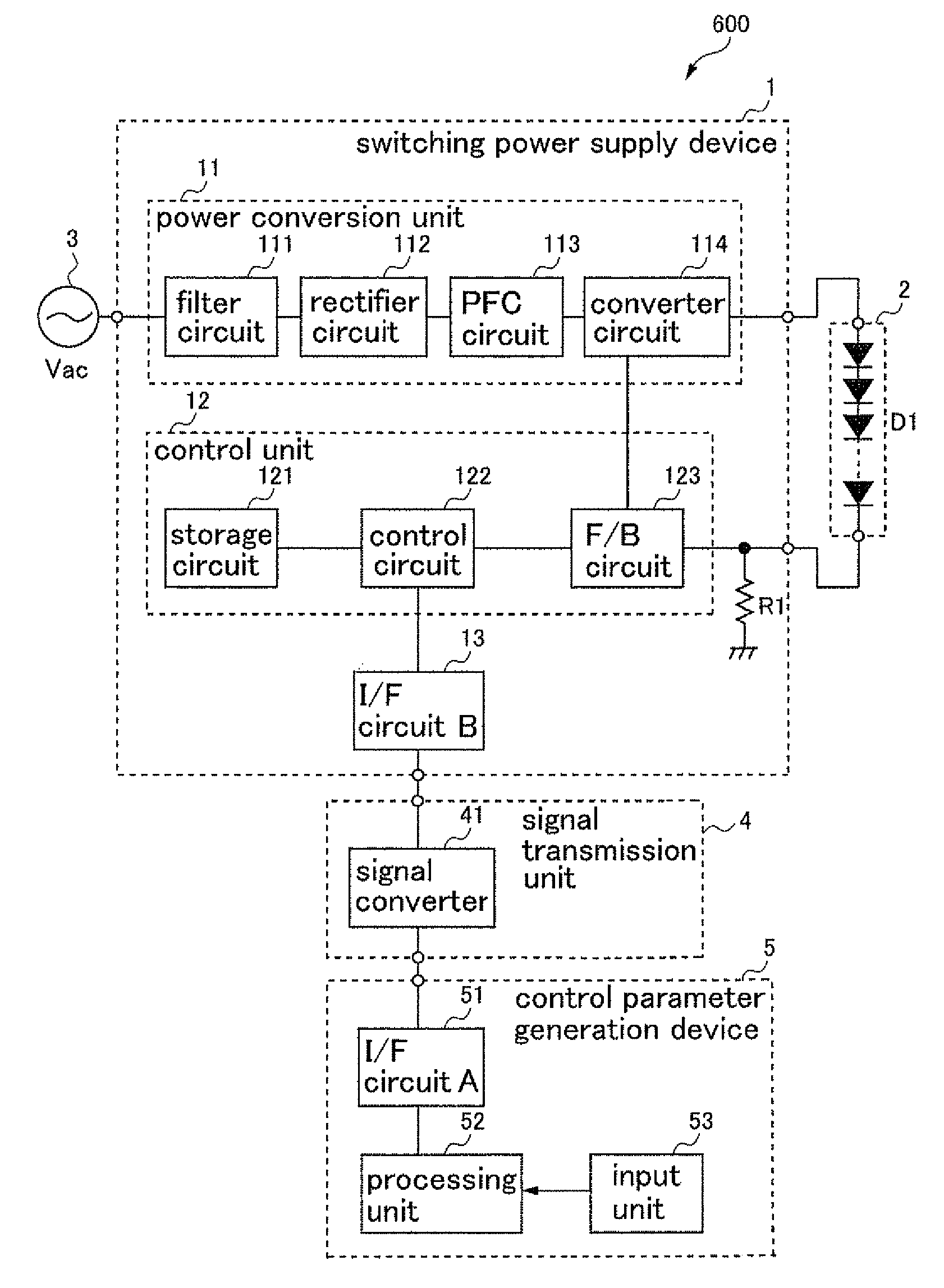
[0071]As described above, according to the power supply device system 600 of the present embodiment, the switching power supply device 1 detects the direct current supplied to the constant current load 2, stores at least a control parameter generated by the host system 5, and generates, based on the detected direct current and the stored control parameter, the driving pulse for the switching element to perform the switching operation so that the direct current supplied to the constant current load 2 becomes substantially constant. As a result thereof, the switching power supply device 1 can control the incorporated switching element using the stored control parameter, thereby it is possible to provide the power supply device system 600 that can change a feature and a specification at a low cost and / or without changing hardware design such as circuit configuration and circuit element constants.

[0072]Furthermore, according to the switching power supply device 1 of ...


PUM


Abstract

A power supply device system including: a switching power supply device converting an alternating voltage to a predetermined direct current by means of a switching operation of a switching element, and supplying the direct current to a load; a control parameter generation device generating a control parameter corresponding to at least one of the alternating voltage and the direct current; and a signal transmission unit disposed between the switching power supply device and the control parameter generation device, transmitting the control parameter to the switching power supply device, wherein the switching power supply device has a control unit detecting the direct current, storing the control parameter, and generating a driving pulse for the switching element to perform the switching operation so that the direct current becomes substantially constant, based on the direct current detected and the control parameter stored.

Description

TECHNICAL FIELD[0001]The present invention relates to a power supply device system, a switching power supply device, a control parameter generation device for the switching power supply device, and a program of the control parameter generation device.BACKGROUND ART[0002]For example, Japanese Unexamined Patent Application Publication No. 2005-116738 (Patent Literature 1) discloses a technology as a power supply device that converts an alternating power voltage with high efficiency, so as to acquire a direct current used to feed an LED (Light Emitting Diode) load, which is driven by a constant current.[0003]According to the technology disclosed by Japanese Unexamined Patent Application Publication No. 2005-116738 (Patent Literature 1), a control signal used in an LED current control circuit is monitored, and, if it is detected that a forward voltage drop across the LED is low, i.e., the LED is efficient and a voltage drop across an FET (Field Effect Transistor) is high, a supply volta...

Claims


Application Information

Patent Timeline
Patent Type & Authority Patents(United States)
IPC IPC(8): H02M5/42H02M7/04H02M7/217
CPCH02M7/04H02M7/217
Inventor NAKAMURA, YOSHIHIRO
Owner MINEBEAMITSUMI INC
Features
  • R&D
  • Intellectual Property
  • Life Sciences
  • Materials
  • Tech Scout
  • Unparalleled Data Quality
  • Higher Quality Content
  • 60% Fewer Hallucinations
Learn More