
Modular printer having narrow print zone

a printer module and print zone technology, applied in printing, power drive mechanisms, inking apparatus, etc., can solve the problems of media web breaking, maintenance of printheads, and limitations on the types and lengths of print jobs that may be performed, so as to reduce the production cost of printhead cartridges, reduce the production cost of printer modules, and facilitate the end user

Active Publication Date: 2015-06-23
MEMJET TECH LTD
View PDF3 Cites 18 Cited by
  • Summary
  • Abstract
  • Description
  • Claims
  • Application Information

AI Technical Summary

Benefits of technology

The patent describes a printer assembly that maximizes print quality while enabling a versatile maintenance regime. It achieves this by minimizing the width of the print zone and placing the printheads relatively proximal and the maintenance stations relatively distal. The printer also ensures smooth lifting and lowering of the printhead with minimal wear and accurate printhead placement in the printing position. Another advantage of the printer assembly is that it does not require true parallelism in the guide posts, which can result in misalignments during lifting and lowering of the printhead. The printer assembly is designed to address these issues and ensure accurate printhead positioning.

Problems solved by technology

A disadvantage of this arrangement is that a media web must be broken in order to perform printhead maintenance.
This maintenance regime therefore places limitations on the types and lengths of print jobs that may be performed.
However, a disadvantage of the printer described in US 2012 / 0092419 is its relatively high cost as well as difficulties in scaling the printer for printing onto wider media widths.
Each carousel crosses the media path in order to perform printhead maintenance, which necessitates breaking the media web.

Method used


Image

  • Modular printer having narrow print zone
  • Modular printer having narrow print zone
  • Modular printer having narrow print zone

Examples


Embodiment Construction

Printer Module Overview

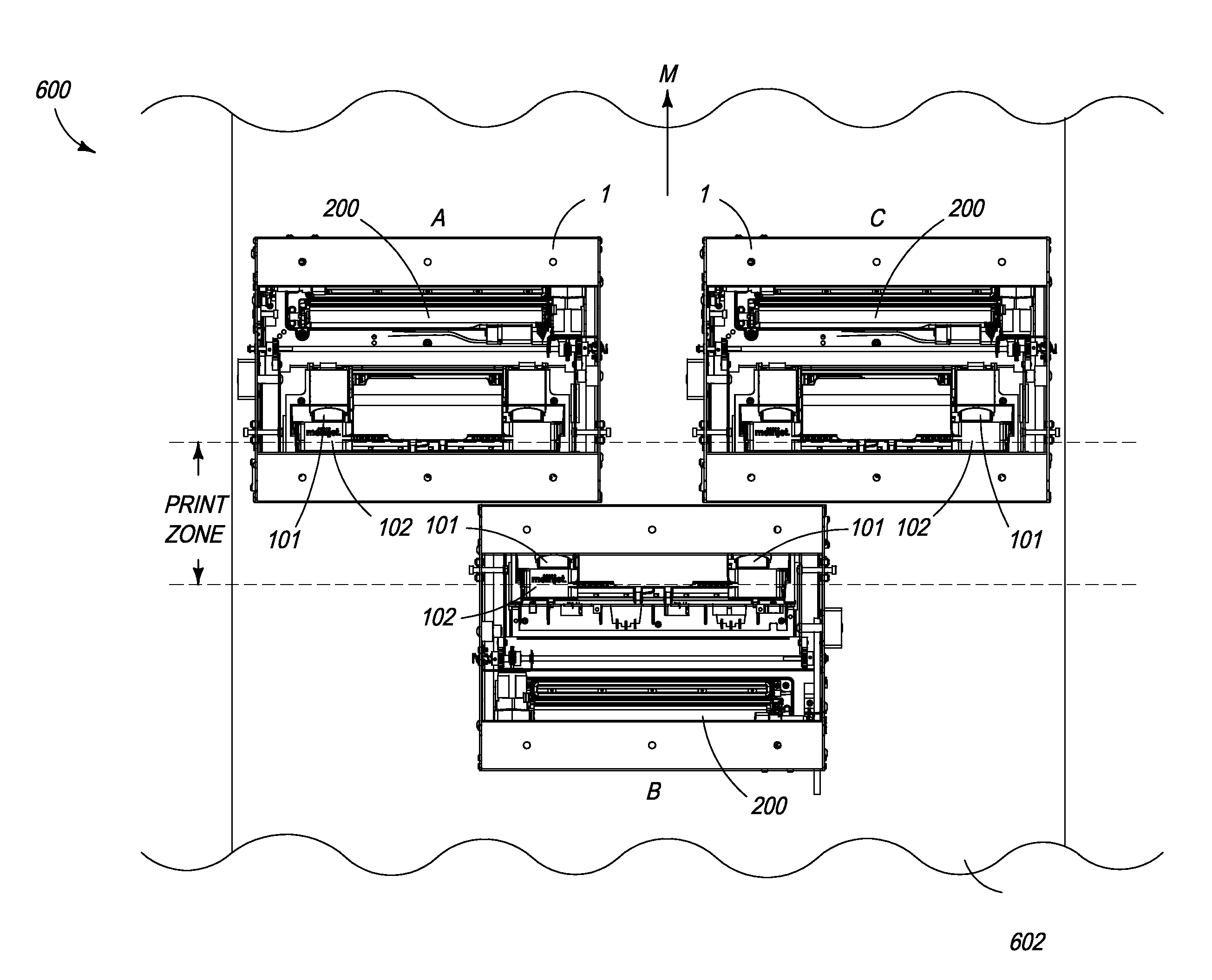
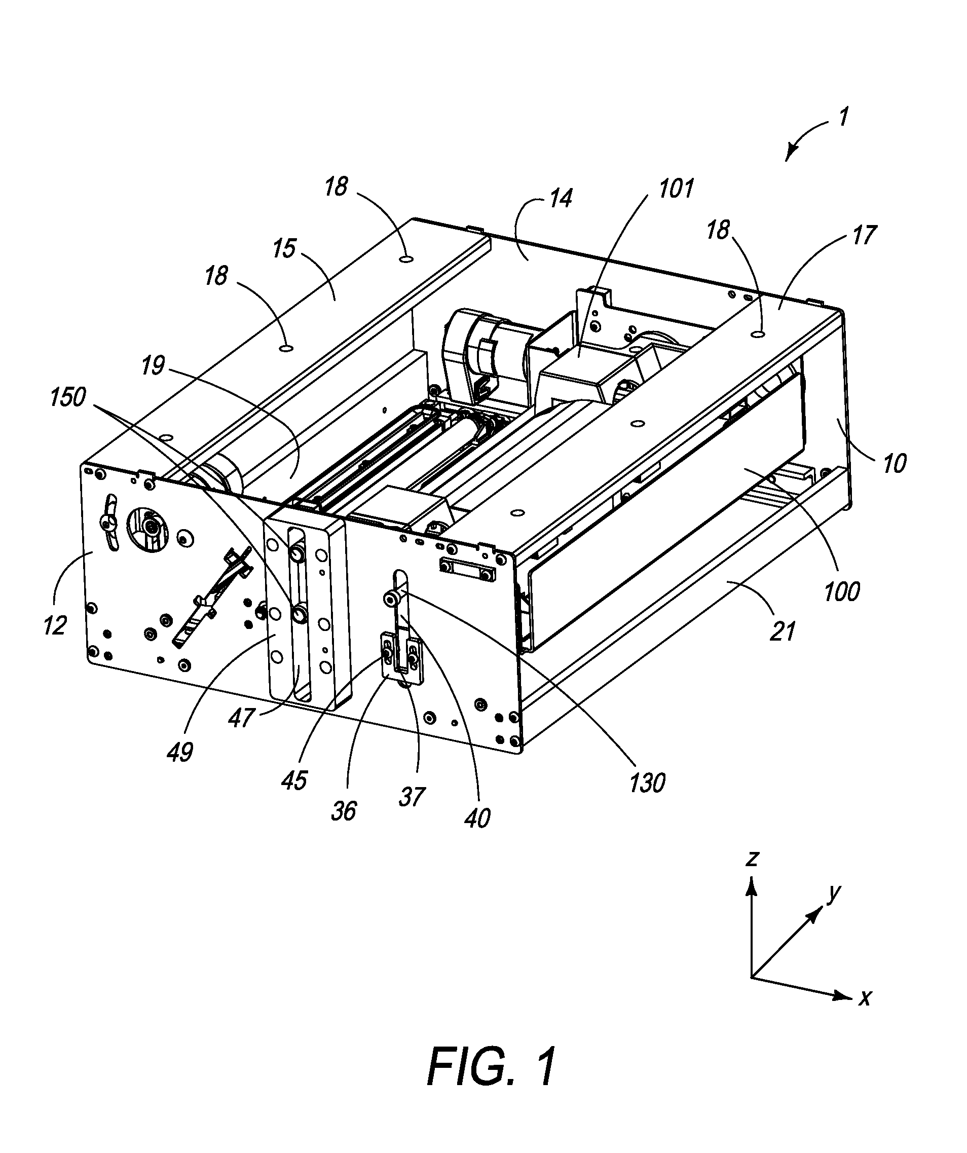
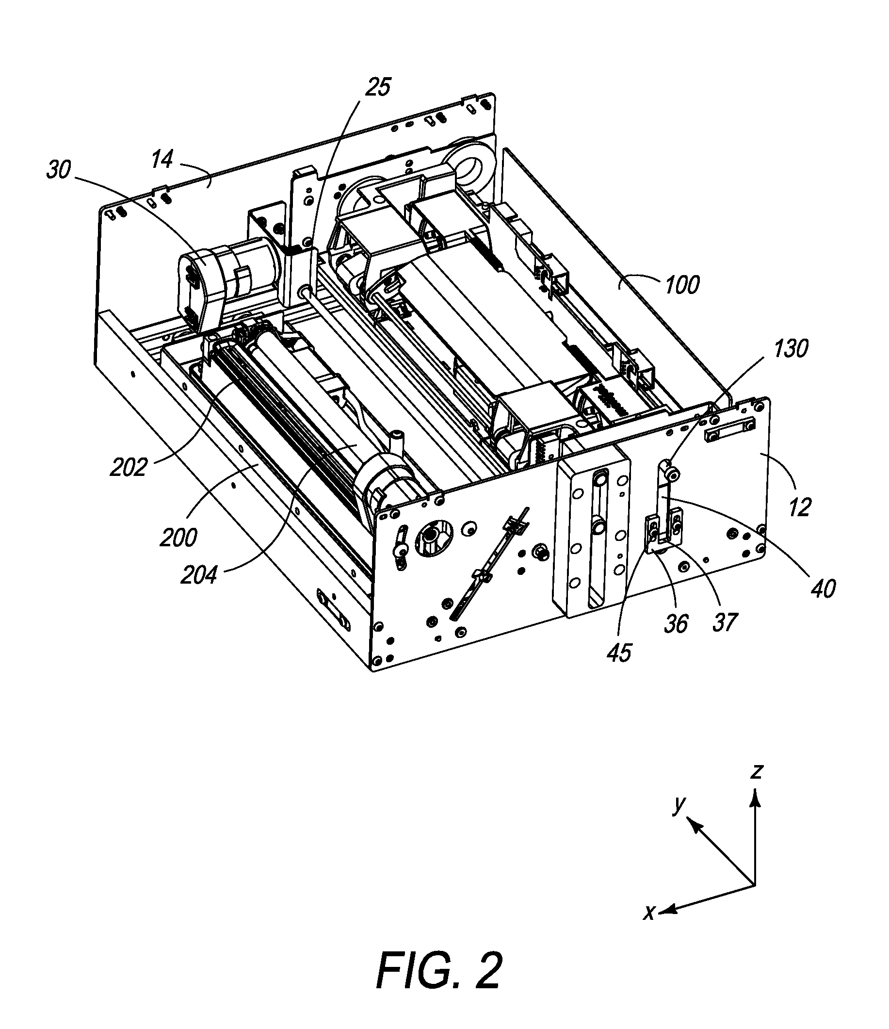
[0121]Referring to FIG. 1, there is shown a printer assembly in the form of a printer module 1 comprising a housing 10 having a first sidewall 12 and an opposite second sidewall 14. The first and second sidewalls 12 and 14 are connected via upper mounting beams 15 and 17, and lower connecting beams 19 and 21 to provide a rigid framework for housing a print engine comprised of a print bar carriage 100 and maintenance sled 200 (see FIG. 5). Each of the mounting beams 15 and 17 has mounting fixtures 18 for mounting the printer module 1 to a gantry or cantilever beam (not shown). Thus, the printer module 1 is configured for suspending over a print media path. Print media, such as a media web, may be fed past the printer module 1 using, for example, suitable feed rollers as is known in the art. The housing 10 has no base to facilitate feeding of the media web past a lower portion of the printer module 1.

[0122]The print bar carriage 100 is slidably received within t...


PUM


Abstract

A modular printer includes: (a) a media feed path defining a media feed direction; (b) a first printer module suspended over the media feed path; and (c) a second printer module suspended over the media feed path and at least partially overlapping the first printer module in the media feed direction. The first and second printer modules have respective first and second printheads and maintenance assemblies. The first and second printheads are relatively proximal to each other with respect to the media feed direction, and the first and second maintenance assemblies are relatively distal from each other with respect to the media feed direction.

Description

FIELD OF THE INVENTION[0001]This invention relates to a printer module and high-speed printers comprising one or more of such printer module(s). It has been developed for printing onto media webs, and particularly for use in conjunction with existing web feed mechanisms, such as those installed in offset printing presses.CO-PENDING APPLICATIONS[0002]The following applications have been filed by the Applicant simultaneously with the present application:[0003]Ser. No. 14 / 473,811 Ser. No. 14 / 473,814[0004]The disclosures of these co-pending applications are incorporated herein by reference. The above applications have been identified by their filing docket number, which will be substituted with the corresponding application number, once assigned.BACKGROUND OF THE INVENTION[0005]Inkjet printing is well suited to the SOHO (small office, home office) printer market. Increasingly, inkjet printing is expanding into other markets, such as label and wideformat printing. High-speed web printing...

Claims


Application Information

Patent Timeline
Patent Type & Authority Patents(United States)
IPC IPC(8): B41J25/00
CPCB41J25/001B41J2/16585B41J25/34B41J25/304B41J2/16535B41J2/16508B41J2202/20B41J2/16505
Inventor CAMPILLO, ALEJANDRORAMASWAMY, RAJANTRAN, TINHLOVELACE, DAVID
Owner MEMJET TECH LTD
Learn More