
Multi-function condiment container

a condiment container and multi-functional technology, applied in the field of condiment packaging, can solve the problems of container messyness, difficulty in adjusting the container, and restrictions on the types of materials, so as to reduce or eliminate the degradation of the condiment packaging, and enhance the grip between the ears

Active Publication Date: 2015-06-23
H J HEINZ COMPANY BRANDS
View PDF170 Cites 29 Cited by
  • Summary
  • Abstract
  • Description
  • Claims
  • Application Information

AI Technical Summary

Benefits of technology

The patent text describes a container for a condiment that has a stable receptacle for use by a consumer. The receptacle has a low, wide, and stable bottom surface to support the container when a food item is thrust into it. The container is made of a material that has a specific thickness and can be stiffened to prevent bending or tipping. The container also has a cover that is attached to the container and is more flexible than the container. The container can be attached to a paperboard container using slits and hooks, and the surface of the container can be treated to improve grip. The lid and container can also have oxygen control barriers to prevent degradation of the condiment. The container includes a finger-access gap for easy gripping.

Problems solved by technology

Notwithstanding the development of condiment containers, a number of difficulties are known to exist with available containers.
More particularly, during use, the containers tend to be messy making them imperfect for use by children, and for use in vehicles when provided at drive-thru food sources.
In addition, in recognition of environmental concerns, some retailers impose restrictions on the types of materials that may be used in products sold or otherwise provided through their retail outlets.
The bonded relationship between the cover and the flange makes it difficult to properly grasp the cover.
Moreover, it is desirable to package condiment containers in closely arranged compact relationship for shipment, but the configuration of the containers often makes this difficult to achieve.
In this manner, access to the condiment through the spout is much more restricted that access to the condiment through the upper edge of the receptacle.

Method used


Image

  • Multi-function condiment container
  • Multi-function condiment container
  • Multi-function condiment container

Examples


first embodiment

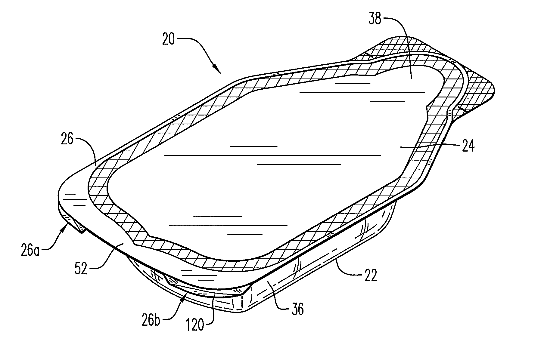
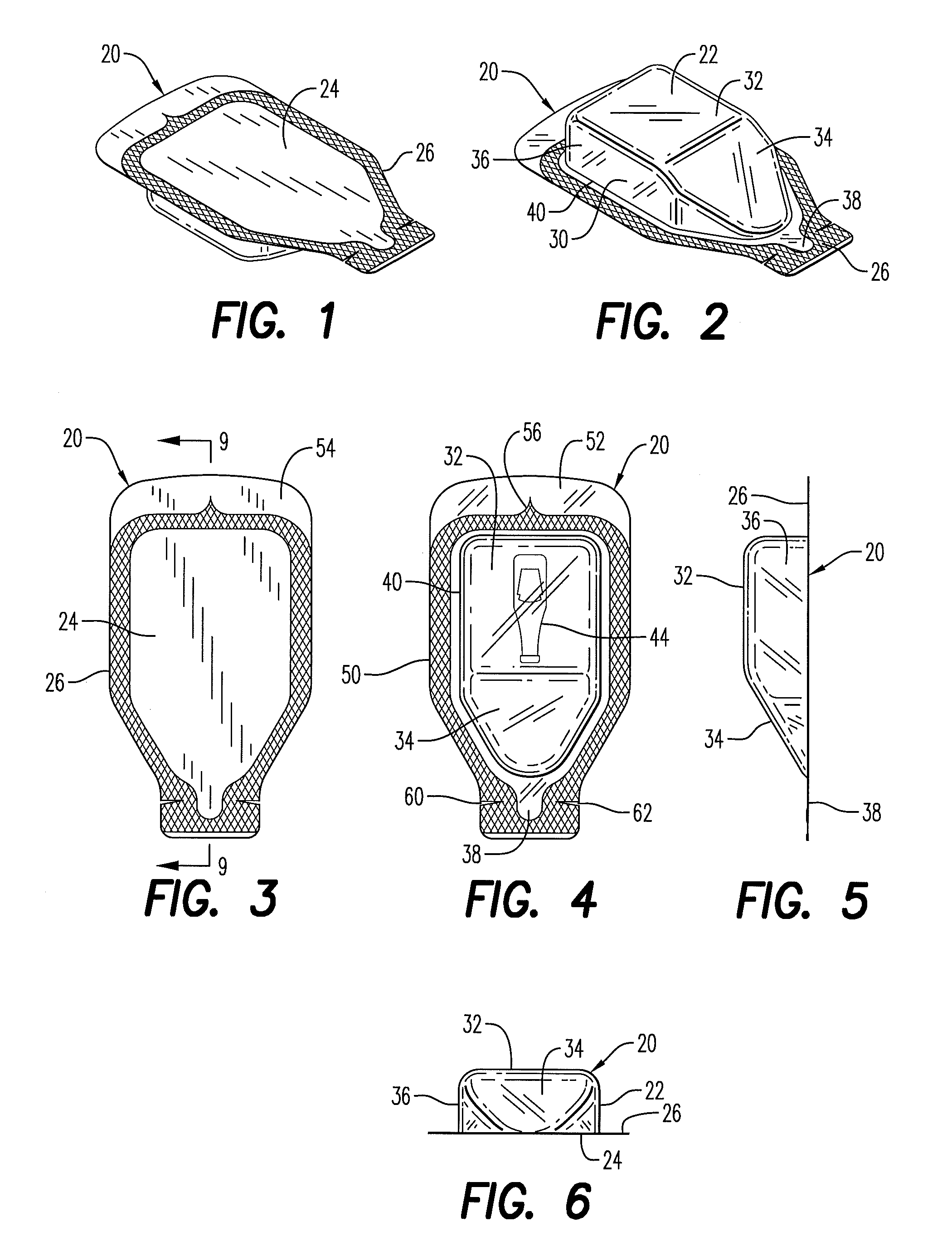
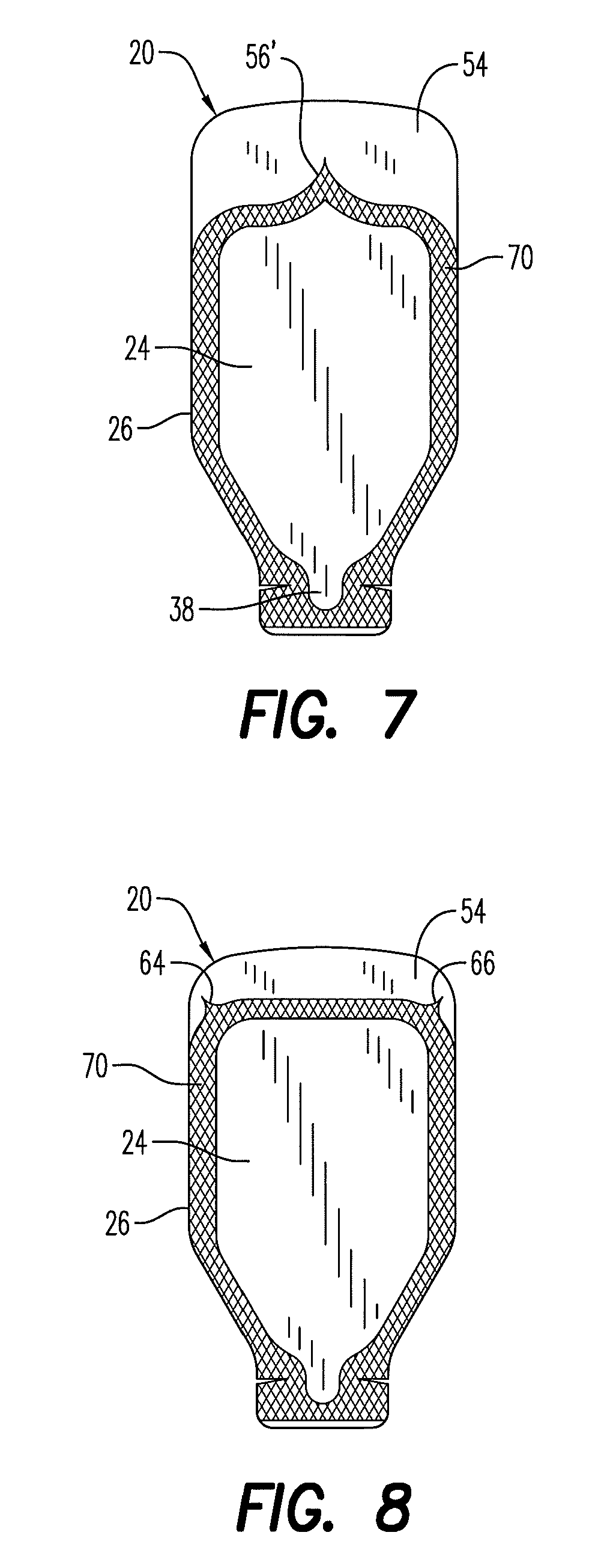
[0072]Turning now to FIG. 1 the condiment container 20 according to this invention is adapted for marketing, and delivery to a consumer as an individual portion of a condiment. The condiment container 20 is formed by a container or cup portion 22 (see FIG. 2) and a lid or cover portion 24 (see FIG. 1) which are sealed together by an adhesive along a flange 26.

[0073]The lid portion 24 is preferably fabricated from a material selected from the group consisting of polyethylene terephthalate (PET), amorphous polyethylene terephthalate (APET), oriented polyethylene terephthalate (OPET), polyester (PE), low density polyester (LDPE), linear low density polyester (LLDPE), metalocene linear low density polyester (mLLDPE), high density polyester (HDPE), metalocene polyester (mPE), ethylene vinyl acetate (EVA), polypropylene (PP), high impact polystyrene (HIPS), foil, ethylene vinyl alcohol (EVOH), polyimide, Nylon, polyvinyl chloride (PVC), and combinations thereof. Where foil is used, that f...

seventh embodiment

[0109]An additional advantageous feature of the seventh embodiment shown in FIGS. 28-40 relates to a configuration of the container sidewall 36 which facilitates compact packaging of a plurality of the containers, for example, in a carton or other packaging device. In that regard, it is desirable to compactly package and transport the containers 20 in such close proximity to one another that the flanges of adjacent containers overlap one another, as shown in FIGS. 37-40. As can be seen in those figures, first and second containers 20a and 20b are arranged with their spouts in alignment in the longitudinal direction Z. The spout 38 of the first container overlies the rear portion of the second container 20b. Additional third and fourth containers 20c and 20d are also arranged with their spouts longitudinally aligned. The third and fourth containers are also disposed adjacent the first and second containers 20a, 20b, respectively, in a lateral direction Z′ with respect to the longitud...

eighth embodiment

[0114]The eighth embodiment, depicted in FIG. 41, shows that the front portion 36a of the sidewall can be inclined relative to the plane of the flange, essentially in the longitudinal direction Z, such that an acute angle is defined between the plane of the front portion 36a and the plane of the flange. Such an arrangement may, for example, be desirable in applications where it is desired to more securely lock or otherwise position the aligned adjacent ends of containers.

[0115]Turning briefly to FIG. 29, a score line 110 may be applied to the container lid or to the container bottom using a laser. For many materials, the score line can be applied mechanically, by laser, and / or by any other suitable means. In some applications where APET is used as the material, mechanical creasing or scoring is not preferred because APET tends to be brittle and may inadvertently break and because the APET material is not planar in the region of the spout. The laser score line 110 may be applied to a...


PUM

PropertyMeasurementUnit
weightaaaaaaaaaa
thicknessaaaaaaaaaa
thicknessaaaaaaaaaa

Abstract

A container for condiments includes a container portion having generally planar bottom, a generally parallel flange, a discharge spout, and a sidewall extending between the bottom and the flange. A generally planar cover portion is secured to the flange by an adhesive such that there exists a non-bonded region between the cover and the flange. At least one section of the flange in the non-bonded region is bent downwardly away from the cover portion to form therebetween a finger-access gap. The sidewall includes a front portion disposed below the spout and extending downwardly with respect thereto. The sidewall front portion is configured to prevent the spout from becoming displaced upwardly in response to the sidewall front portion being contacted by the rear portion of another container in a package of the containers.

Description

[0001]This is a continuation-in-part of concurrently filed U.S. application Ser. No. 12 / 766,091 naming the same inventive entity. Both the concurrently filed application and the subject continuation-in-part application claim the benefit of the Apr. 23, 2009, filing date of Provisional Application No. 61 / 202,968.BACKGROUND OF THE INVENTION[0002]The present invention relates generally to packaging for condiments. More particularly, the present invention concerns condiment packaging adapted for opening in at least two different ways.[0003]Condiment packaging has evolved over the years, starting with basic glass bottles and jars for display and sale of condiments, including without limitation ketchup, mustard, mayonnaise, sauces, and the like. That basic packaging later included larger capacity bottles and jars, and then containers made from synthetic plastic materials. Eventually, the packaging concepts turned to providing packaging suitable for individual portions of the condiments.[0...

Claims


Application Information

Patent Timeline
Patent Type & Authority Patents(United States)
IPC IPC(8): B29D22/00B65D21/02B65D85/72B65D75/32
CPCB65D21/0202B65D75/326B65D85/72B65D2221/00B65D2313/00
Inventor CALDWELL, CRAIG S.MARSHALL, JOHNRASILE, WILLIAM F.
Owner H J HEINZ COMPANY BRANDS
Learn More