Unbalance type exciter for a soil compaction device

a soil compacting device and unbalance type technology, applied in the field of unbalance type exciter for soil compacting device, to achieve the effect of cost-effective and optimal vibration behaviour of rollers

Inactive Publication Date: 2015-06-23
AMMANN SCHWEIZ
View PDF11 Cites 4 Cited by
  • Summary
  • Abstract
  • Description
  • Claims
  • Application Information

AI Technical Summary

Benefits of technology

[0009]Accordingly, a first aspect of the invention concerns an unbalance type exciter for a soil compaction device. The unbalance type exciter comprises a carrying structure, at which an unbalance weight by means of a bearing is supported in a rotatable manner around a rotation axis which in the intended use is stationary with respect to the carrying structure, for generating of an intermittent exciting force by means of which the carrying structure in the intended use can be caused to vibrate. The bearing of the unbalance weight is completely or partially arranged within the space, which is circled by the unbalance weight during its rotation about the rotation axis, or, in other words, which is enclosed by the flight path of the unbalance weight. Owing to the fact that this space is used for receiving at least part of the bearing of the unbalance weight or of the rotatable component carrying the unbalance weight, respectively, it becomes possible to provide unbalance type exciters having very small axial overall length.

Problems solved by technology

However, especially in case of relative narrow soil compacting devices like trench rollers, there is the problem that the unbalance type exciters known today, when providing a suitable exciting power comprise an overall length which makes it difficult or even impossible to arrange them axial in line with the roller drive in the rotational centre of the roller, what is desirable since in that case the starting point of the exciting forces substantially coincides with the centre of mass of the roller arrangement formed in this way so that an optimal vibration behaviour of the rollers can be achieved and the remaining structure of the machine is exposed only to minor additional load due to the exciting forces.

Method used


Image

  • Unbalance type exciter for a soil compaction device
  • Unbalance type exciter for a soil compaction device
  • Unbalance type exciter for a soil compaction device

Examples


Embodiment Construction

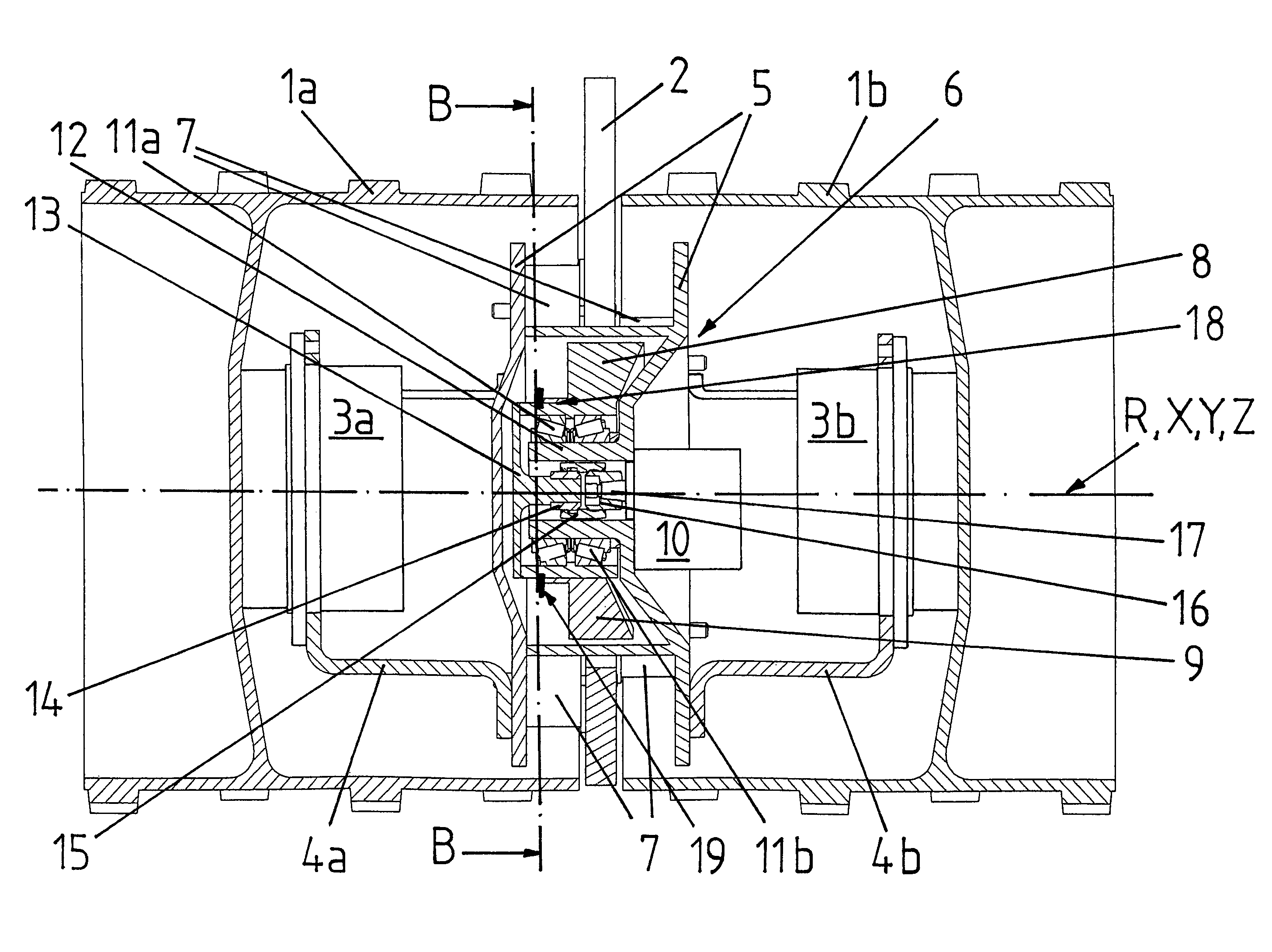
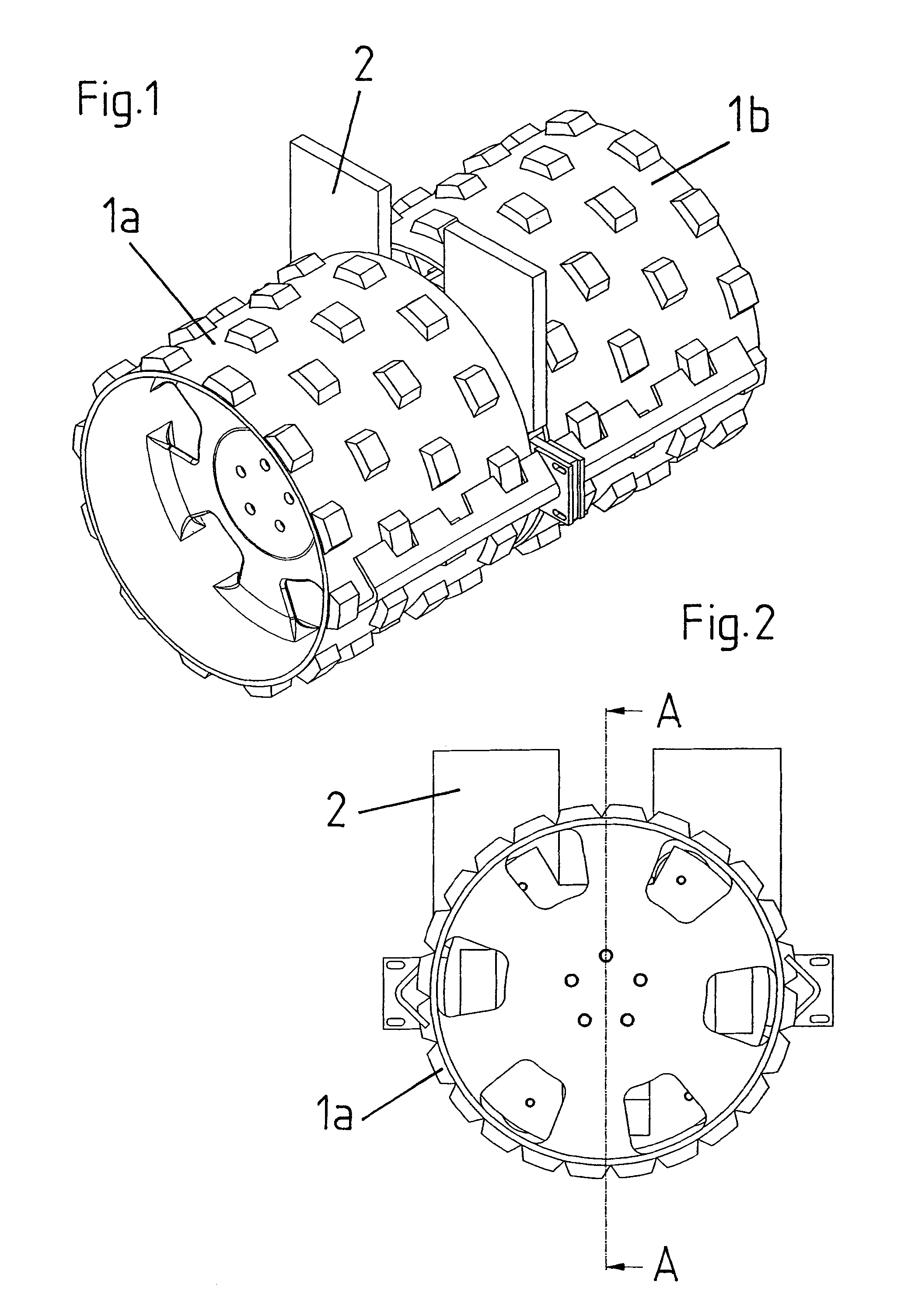
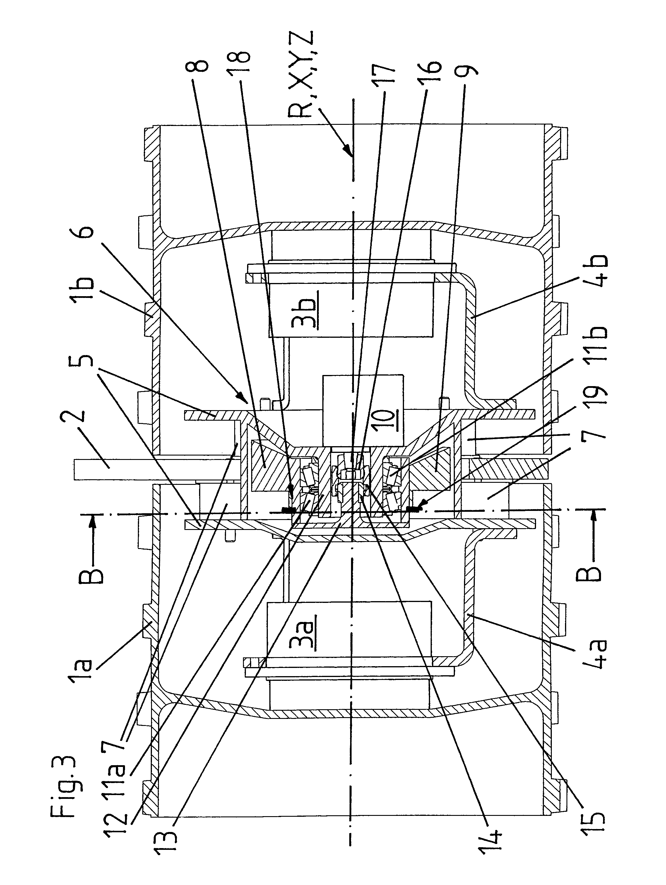
[0037]FIG. 1 shows a roller arrangement according to the invention for a vibration excited trench roller in a perspective top view. The roller arrangement comprises two nubby rollers 1a, 1b of identical diameter, which are arranged side by side with coinciding rotation axis X, and a connecting element 2 for connecting the roller arrangement to the chassis of a trench roller to be formed therewith.

[0038]The connection element 2 radially protrudes between the two rollers 1a, 1b over the outer boundaries of the rollers 1a, 1b and within the rollers 1a, 1b is connected to them in such a manner that the rollers 1a, 1b can be rotated about their rotation axis X relative to the connecting element 2 and the chassis of the trench roller to be formed with the roller arrangement can be supported via the connecting element 2 on the rollers 1a, 1b. The ends of the rollers 1a, 1b which are facing away from the connecting element 2 form the axial boundaries of the roller arrangement.

[0039]As can b...


PUM


Abstract

The invention relates to an unbalance type exciter (6) for a soil compaction device. This exciter comprises a carrying structure (5) as well as an unbalance weight (8, 9), which by means of a bearing (11a, 11b) is supported at the carrying structure (5) in rotatable manner around a rotation axis (Y) which in the intended use is stationary with respect to the carrying structure (5), for generating an intermittent exciting force for causing the carrying structure (5) in the intended use to vibrate. The bearing (11a, 11b) of the unbalance weight (8, 9) is arranged at least partially within the space which is circled by the unbalance weight (8, 9) when rotating around the rotation axis (y). Owing to the fact that this space is used for receiving at least part of the bearing of the unbalance weight (8, 9) it becomes possible to provide unbalance type exciters (6) having very small axial overall length.

Description

CROSS REFERENCE TO RELATED APPLICATIONS[0001]This application claims the priority of PCT Application No. PCT / CH2011 / 000166, filed on Jul. 15, 2011, the disclosure of which is incorporated herein by reference in its entirety.TECHNICAL FIELD[0002]The invention concerns an unbalance type exciter for a soil compacting device, a roller arrangement comprising the unbalance type exciter as well as a vibratory roller comprising the roller arrangement according to the preambles of the independent claims.BACKGROUND OF THE INVENTION[0003]Unbalance type exciter serve for generating exciting forces changing over time, by means of which components coupled to the exciter can be caused to vibrate. They are employed in many technical fields, e.g. in vibrating conveyors, in vibrating screens, in compacting devices like e.g. vibratory plates or vibratory rollers, in vibratory pile driving devices and in vibration excited drilling and cutting devices.[0004]For generating the exciting forces, depending ...

Claims


Application Information

Patent Timeline
Patent Type & Authority Patents(United States)
IPC IPC(8): E01C19/28E02D3/074G01V1/153
CPCE01C19/286E02D3/074G01V1/153
Inventor SCHARER, MARTINANLIKER, CHRISTOPH
Owner AMMANN SCHWEIZ
Why Eureka
Try Eureka