Wireless communication system provided in aircraft for communicating using plural wireless channels

a wireless communication and aircraft technology, applied in wireless communication services, network topologies, broadcast specific applications, etc., can solve problems such as radio wave interference, interference between channels, radio wave interference, etc., to reduce the mechanism of transmission waiting from functioning, reduce the interference between channels, and reduce the error of wireless packets caused by radio wave interferen

Active Publication Date: 2015-06-23
PANASONIC INTPROP MANAGEMENT CO LTD
View PDF23 Cites 1 Cited by
  • Summary
  • Abstract
  • Description
  • Claims
  • Application Information

AI Technical Summary

Benefits of technology

The present invention provides a wireless communication system and a wireless channel allocation method that can reduce interference between channels and improve wireless transmission quality. This is achieved by allocating wireless channels with radio wave shields between them, and preferably on different aisles of an aircraft. The method and system do not require complex detection and reduction procedures, and can be implemented with simple apparatus. This allows for wideband and high-quality wireless transmission.

Problems solved by technology

However, the above-stated prior arts have the following problems.
That is, one channel may possibly suffer the adjacent channel interference directly from the adjacent zone without wireless reduction.
Further, even if the same channels are not present in the adjacent wireless zone interval, the distance between the same channels is closer and radio wave interference may occur from the same channels when a range of each zone is narrow.
Moreover, even if adjacent sectors use different frequencies, the sectors suffer radio wave interference from the same channels because of, for example, the small distance between the same channels in a manner similar to that of the Patent Document 4.
In addition, the method of the Patent Document 6 needs to measure received intensities, include determination means, and perform time-division transmission, disadvantageously resulting in complicated configuration.

Method used


Image

  • Wireless communication system provided in aircraft for communicating using plural wireless channels
  • Wireless communication system provided in aircraft for communicating using plural wireless channels
  • Wireless communication system provided in aircraft for communicating using plural wireless channels

Examples


first embodiment

[0084

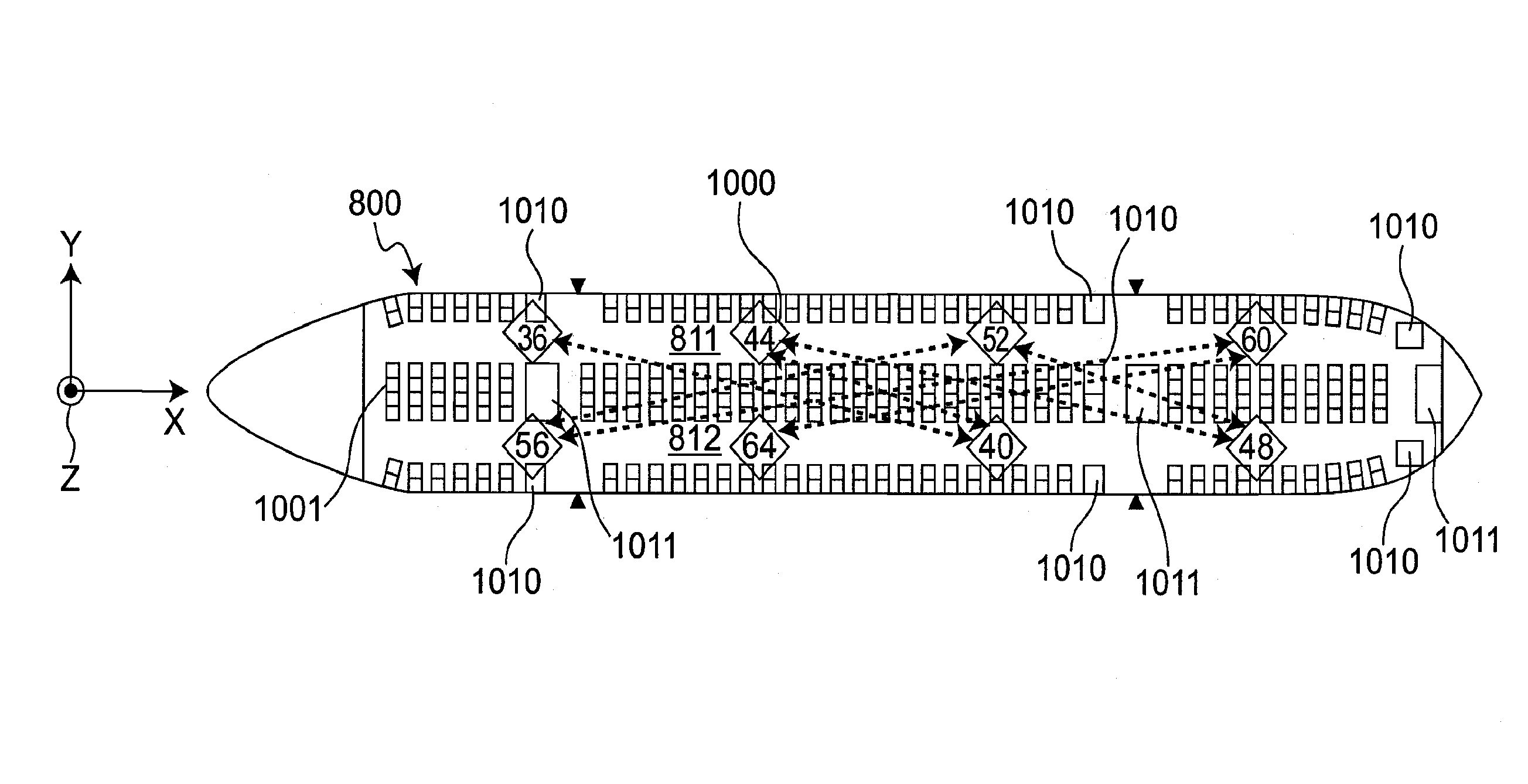
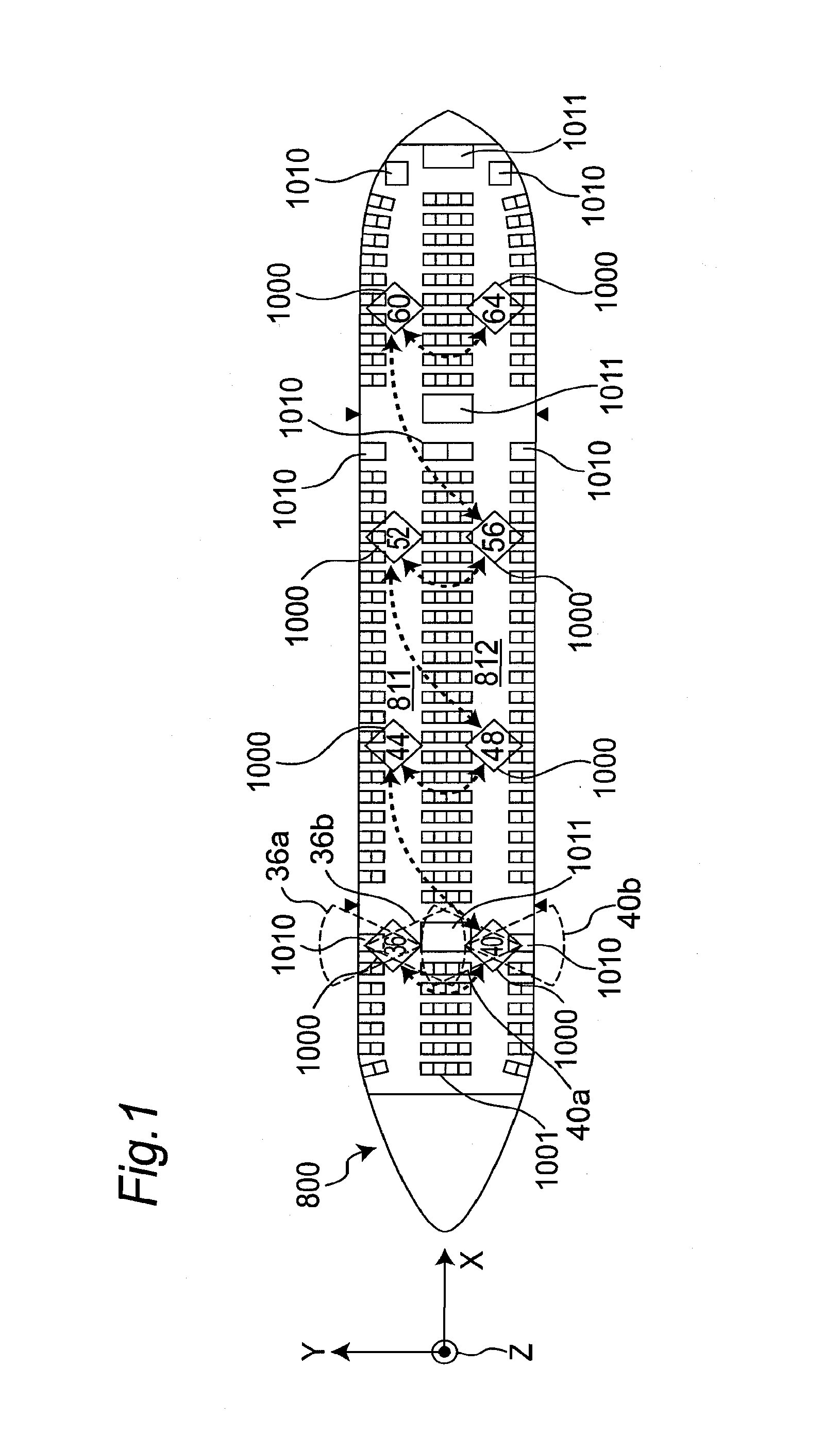
[0085]In a first embodiment of the present invention, a method of reducing the adjacent channel interference will be described. FIG. 1 is a cross-sectional view showing an AV data wireless delivery system that is a so-called aircraft entertainment system including a plurality of wireless access point units 1000 allocated in an aircraft 800, and showing a first allocation example of wireless channels of the respective wireless access point units 1000 according to the first embodiment of the present invention. The important point of the present embodiment is that wireless client devices 504 using adjacent channels are allocated in different aisles 811 and 812, respectively, and that the influence of interference is eliminated by the radio wave shields between the aisles 811 and 812. The two aisles 811 and 812 of the aircraft 800 shown in FIG. 1 extend in the longitudinal direction (X direction) of the aircraft, and are in parallel to each other.

[0086]Referring to FIG. 1, each of ...

second embodiment

[0108

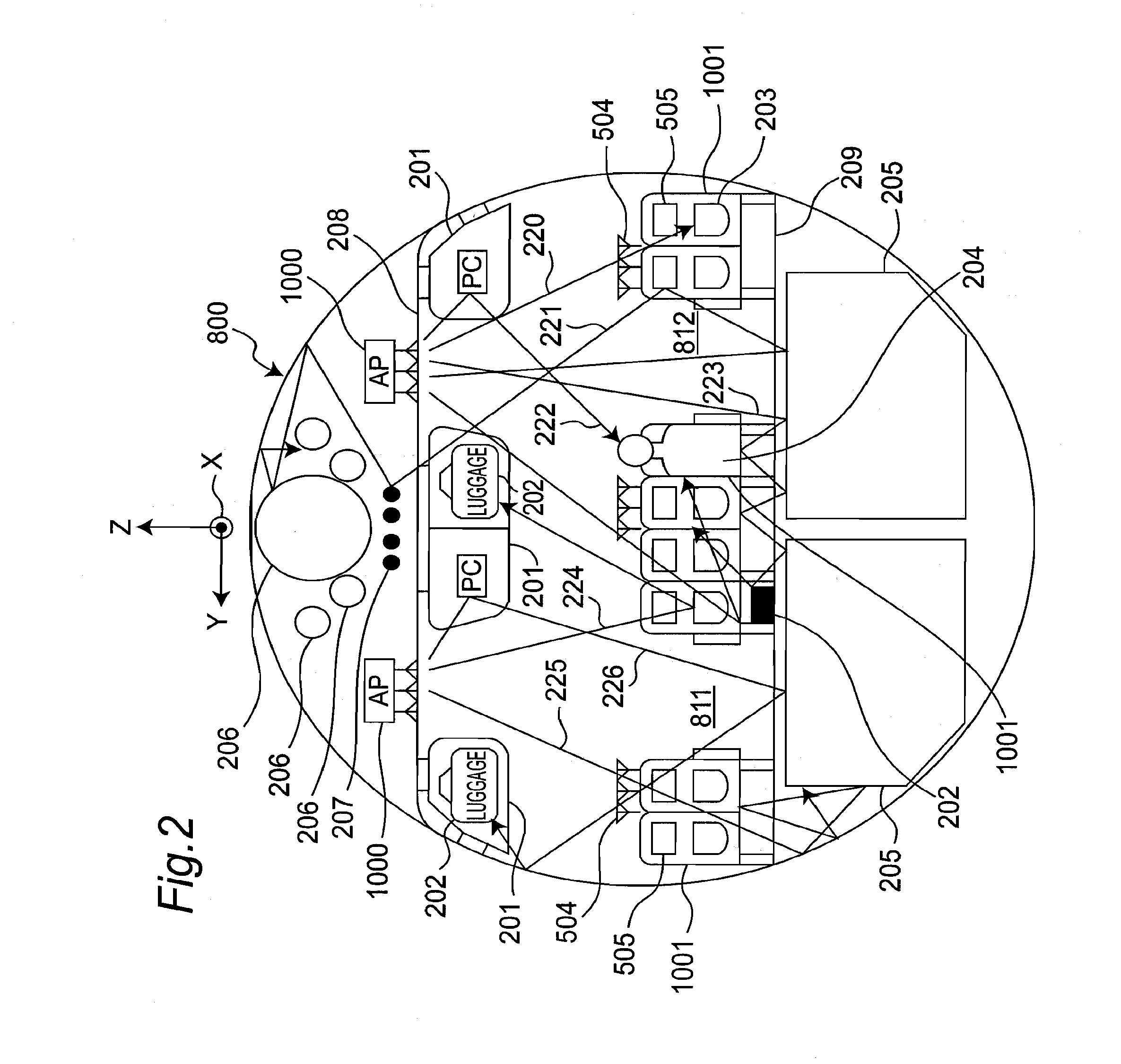
[0109]FIG. 6 is a cross-sectional view showing a second allocation example of wireless channels of the respective wireless access point units 1000 according to a second embodiment of the present invention. FIG. 6 is a cross-sectional view of a passenger compartment of an aircraft 800 in a manner similar to that of FIG. 1. In the present embodiment, in a manner similar to that of the first embodiment, the method will be described, that includes eliminating an influence of interference by the radio wave shields between aisles 811 and 812 by allocating the wireless stations of the respective wireless access point units 100 using adjacent channels on the different aisles 811 and 812, respectively, and that further includes reducing the influence of interference by making a distance between the wireless access point units 1000 using the adjacent channels larger in a cross direction (X direction) of an airframe.

[0110]Referring to FIG. 6, a wireless channel number is written in each o...

third embodiment

[0111

[0112]FIG. 7 is a cross-sectional view showing a third allocation example of wireless channels of the respective wireless access point units 1000 according to a third embodiment of the present invention, and FIG. 7 is a cross-sectional view of a passenger compartment of an aircraft 800 in a manner similar to that of FIG. 1. Referring to FIG. 7, the sixteen wireless access point units 1000 including the same channels are allocated. In the present embodiment, the influence of interference is eliminated by the radio wave shields between aisles 811 and 812 by allocating the wireless stations of the wireless access point units 100 using the same channel on the different aisles 811 and 812, respectively.

[0113]In an AV data wireless delivery system, the use of many wireless access points 1000 is considered so as to improve the total band of the entire system. For example, in the present embodiment, the band corresponding to eight channels from the channel 36 to the channel 64 is used....


PUM


Abstract

In a wireless communication system including a plurality of wireless stations provided in a structure having a radio wave shield arranged at a fixed position, at least one of two wireless stations using an identical wireless channel and two wireless stations using wireless channels adjacent to each other are allocated on both sides of the radio wave shield, respectively. In this case, the structure is an aircraft, and the two wireless stations are allocated on different aisles of the aircraft, respectively. In addition, the two wireless stations are allocated to be apart from each other in a longitudinal direction of the aircraft.

Description

TECHNICAL FIELD[0001]The present invention relates to a wireless communication system provided in a structure such as an aircraft for holding wireless communication using a plurality of wireless channels.BACKGROUND ART[0002]Conventionally, a wireless communication system using a plurality of wireless stations that includes wireless communication units transmitting and receiving wireless signals, respectively, has been put to practical use. For example, each of Patent Documents 1 and 2 discloses an audio and video data wireless delivery system (the audio and video data will be referred to as an AV data hereinafter) in an aircraft. Patent Document 3 proposes a wireless communication system using a wireless local area network (the local area network will be referred to as a LAN hereinafter) in a vehicle. As a wireless communication unit of the wireless LAN system, the products compliant with the IEEE802.11 standard (See, for example, Non-Patent Document 1), for example, has been put to...

Claims


Application Information

Patent Timeline
Patent Type & Authority Patents(United States)
IPC IPC(8): H04W4/00H04W74/08H04H20/62H04B7/185H04W84/00
CPCH04W74/0816H04H20/62H04B7/18506H04W84/005
Inventor HIGASHIDA, MASAAKI
Owner PANASONIC INTPROP MANAGEMENT CO LTD
Why Eureka
Try Eureka