
Turboshaft engine attached to a pylon of the fuselage of an aircraft by a failsafe suspension system

a technology of suspension system and turboshaft engine, which is applied in the direction of aircraft power plants, power plant construction, power plant types, etc., can solve the problems of complicated mounting of rods, the risk of connecting rods hitting the fastening with turboshaft engines or the pylon, etc., and achieve the effect of convenient rod mounting

Active Publication Date: 2015-06-30
SN DETUDE & DE CONSTR DE MOTEURS DAVIATION S N E C M A
View PDF18 Cites 6 Cited by
  • Summary
  • Abstract
  • Description
  • Claims
  • Application Information

AI Technical Summary

Benefits of technology

The invention describes a flexible element that allows a rod to avoid contact with a turboshaft engine and isolate it from vibrations while still maintaining the necessary load limitations on the suspensions. The flexible element can take the form of a ring-shaped cylindrical element housed in one of the ends of the connecting rod, which is articulated at either the turboshaft engine or the pylon. The flexible element can also be in the form of concentric cylindrical layers that allow the rod to adjust its length. The technical effect is a safer and reliable solution for attaching a rod to a turboshaft engine and pylon while maintaining the suspension load limitations.

Problems solved by technology

Although providing reinforced safety in the event of the rear suspension system breaking down, mounted in such a manner with clearance, in normal operation the connecting rod runs the risk of hitting the fastening with the turboshaft engine or the pylon due to the vibrations and other displacements produced and generated by the operation of same.
Added to this is the restricted space between the turboshaft engine and the pylon which makes the mounting of the rod complicated.

Method used


Image

  • Turboshaft engine attached to a pylon of the fuselage of an aircraft by a failsafe suspension system
  • Turboshaft engine attached to a pylon of the fuselage of an aircraft by a failsafe suspension system
  • Turboshaft engine attached to a pylon of the fuselage of an aircraft by a failsafe suspension system

Examples


first embodiment

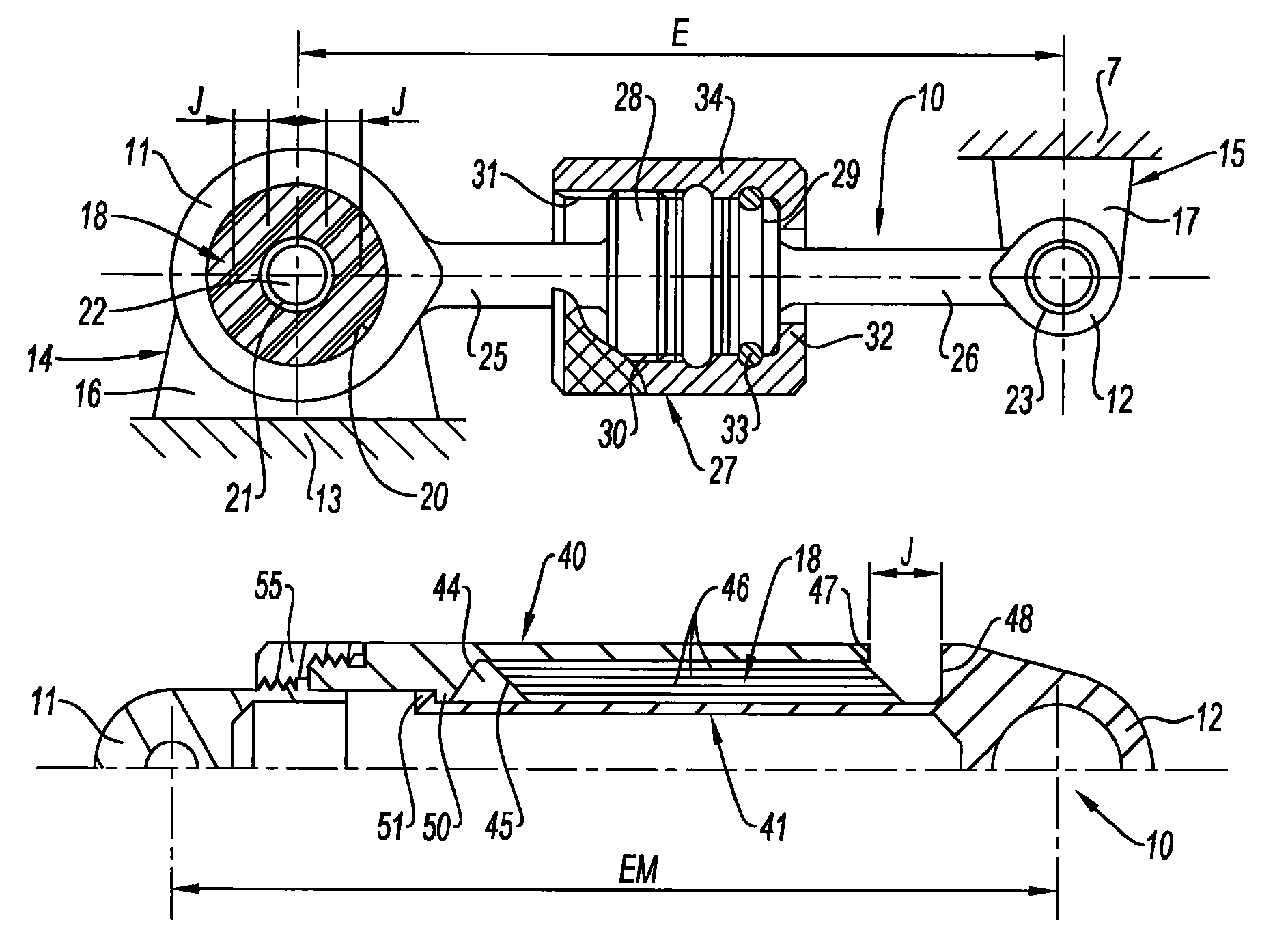
[0036]In a first embodiment shown in FIG. 4, an elastically deformable, flexible element 18 is arranged at one of the ends 11 and 12 of the connecting rod 10, which ends terminate in the usual manner in a ring-shaped cylindrical form as an eyelet. The distance separating the centers of the ring-shaped ends 11, 12 defines the center distance E of the rod 10. In FIG. 4, it can be seen that the flexible element 18 is arranged in the ring-shaped end 11 of the rod 10 which co-operates with the fastening 14 with the lug 16 of the corresponding casing 13 of the turboshaft engine 2. Therefore structurally, said flexible element 18 has a ring-shaped cylindrical form becoming integrated between the inner lateral surface 20 of the ring-shaped end 11 and the outer lateral surface 21 of the cylindrical articulation axis 22 connecting the lug 16 to the end 11.

[0037]The material used to realize the flexible element 18 is, for example, a silicone based elastomer, notably capable of thermally resist...

second embodiment

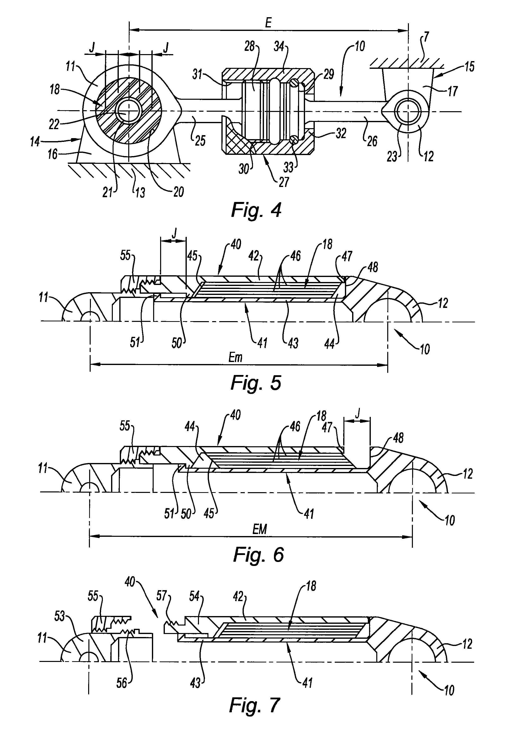
[0043]In the second embodiment shown in FIGS. 5, 6 and 7, instead of maintaining the clearance J by means of the flexible element 18 between one of the lugs of the fastenings and the corresponding articulation axis, the fail-safe axial clearance J is integrated directly in the connecting rod 10, allowing it to vary the length thereof (center distance E) within the predetermined clearance, without passing any force whatsoever through it.

[0044]To this end, in this case too the connecting rod 10 is made up of two distinct parts 40, 41, but here they are arranged together telescopically in a coaxial manner. A first outer tubular part 40 is defined in order to end in the ring-shaped end 11 capable of being articulated at the lug 16 (not shown) of the fastening of the casing of the turboshaft engine 2. A second inner cylindrical part 41, preferably tubular because of the gain in mass, is engaged in the first tubular part 40 and ends in the other ring-shaped end 12 capable of being articul...


PUM


Abstract

A suspension system including a front suspension plane located at an intermediate turboshaft engine casing and connecting same to a pylon, a rear suspension plane located at an exhaust casing of the turboshaft engine and connecting same to the pylon, and a failsafe intermediate suspension plane located between the front and rear planes and including at least one connecting rod connecting the turboshaft engine having a structural outer casing to the pylon, the connecting rod mounted on the turboshaft engine with a predetermined clearance that renders the connecting rod inoperable while the suspension system of the rear plane is operating. The connecting rod is advantageously arranged between the outer casing and the pylon, and an element made of a flexible material is combined with the connecting rod to create the predetermined clearance by an elastically deformable nature thereof.

Description

BACKGROUND OF THE INVENTION[0001]1. Field of the Invention[0002]The present invention concerns a suspension system for a turboshaft engine or similar at a pylon of an aircraft making it possible to ensure that said turboshaft engine is secured in total safety to the structure of the aircraft.[0003]2. Description of the Related Art[0004]The term suspension refers in a general manner to all the different parts necessary for securing the turboshaft engine to the pylon, such as notably the fastenings, articulations, axes, ball-and-socket joints, rods, arms, collars, fittings, etc. . . . that are usually found for this purpose.[0005]In general, the suspension system is located and contained in specific planes of the turboshaft engine which are parallel to each other and at right angles with respect to the longitudinal axis of said turboshaft engine. In this way, it is made up by at least one front suspension plane located at an intermediate turboshaft engine casing and connecting same to...

Claims


Application Information

Patent Timeline
IPC IPC(8): B64D27/26B64D27/14
CPCB64D27/26B64D27/14B64D27/40
Inventor BELLABAL, FRANCOISSEIZE, GUILHEMVINCENT, THOMAS
Owner SN DETUDE & DE CONSTR DE MOTEURS DAVIATION S N E C M A
Learn More