Arrangement for supplying oil to a brake

a technology for supplying oil and brakes, which is applied in the direction of gear lubrication/cooling, axially engaging brakes, belts/chains/gearrings, etc., can solve the problems of inability to mount the oil pump with the brake, and the inability of centrifugal pumps to function properly, so as to achieve high and reliable brake torque and facilitate oil cooling

Inactive Publication Date: 2015-06-30
VOLVO CONSTR EQUIP AB
View PDF18 Cites 6 Cited by
  • Summary
  • Abstract
  • Description
  • Claims
  • Application Information

AI Technical Summary

Benefits of technology

[0004]In order to improve the brake capacity and to prevent brake fading, it is known to use an oil pump to actively supply the brake with oil instead of just letting the brake discs be immersed in the oil. An oil pump will improve the oil flow through the disc brake, which in turn will improve the cooling capacity of the oil. The oil will take up the heat from the brake and will distribute the heat to the larger part of the wheel hub where the brake is positioned. The cooling surface for the oil is thus enlarged. The brake capacity may be improved further by increasing the oil volume and / or the cooling of the oil. This can be done by using an external oil reservoir and / or an external oil cooler.
[0016]In a further advantageous development of the inventive oil supply arrangement, the arrangement is mounted in an axle casing having one or more oil channels for transporting the heated oil from the brake to a remote inner part of the axle. In this way, the axle casing can help to cool the oil due to a larger contact surface for the oil. Further, the cooling of the oil is aided due to the fact that the oil is distributed over a larger surface inside the axle. When the brake is mounted in the wheel hub of a vehicle, it is also possible to mix the oil of two adjacent wheel hubs, which may be of advantage if the brake on one side of the vehicle is used more than the other.

Problems solved by technology

Due to the low rotational speed of the wheel and thus of the brake, it is not possible to mount the oil pump with the brake since the oil flow from an oil pump rotating with such a low rotational speed will not be enough to pump a sufficient amount of oil through the wet disc brake.
This is especially the case for centrifugal pumps that will not function properly at low rotational speeds.

Method used


Image

  • Arrangement for supplying oil to a brake
  • Arrangement for supplying oil to a brake
  • Arrangement for supplying oil to a brake

Examples


Embodiment Construction

[0022]The embodiments of aspects of the invention with further developments described in the following are to be regarded only as examples and are in no way to limit the scope of the protection provided by the patent claims.

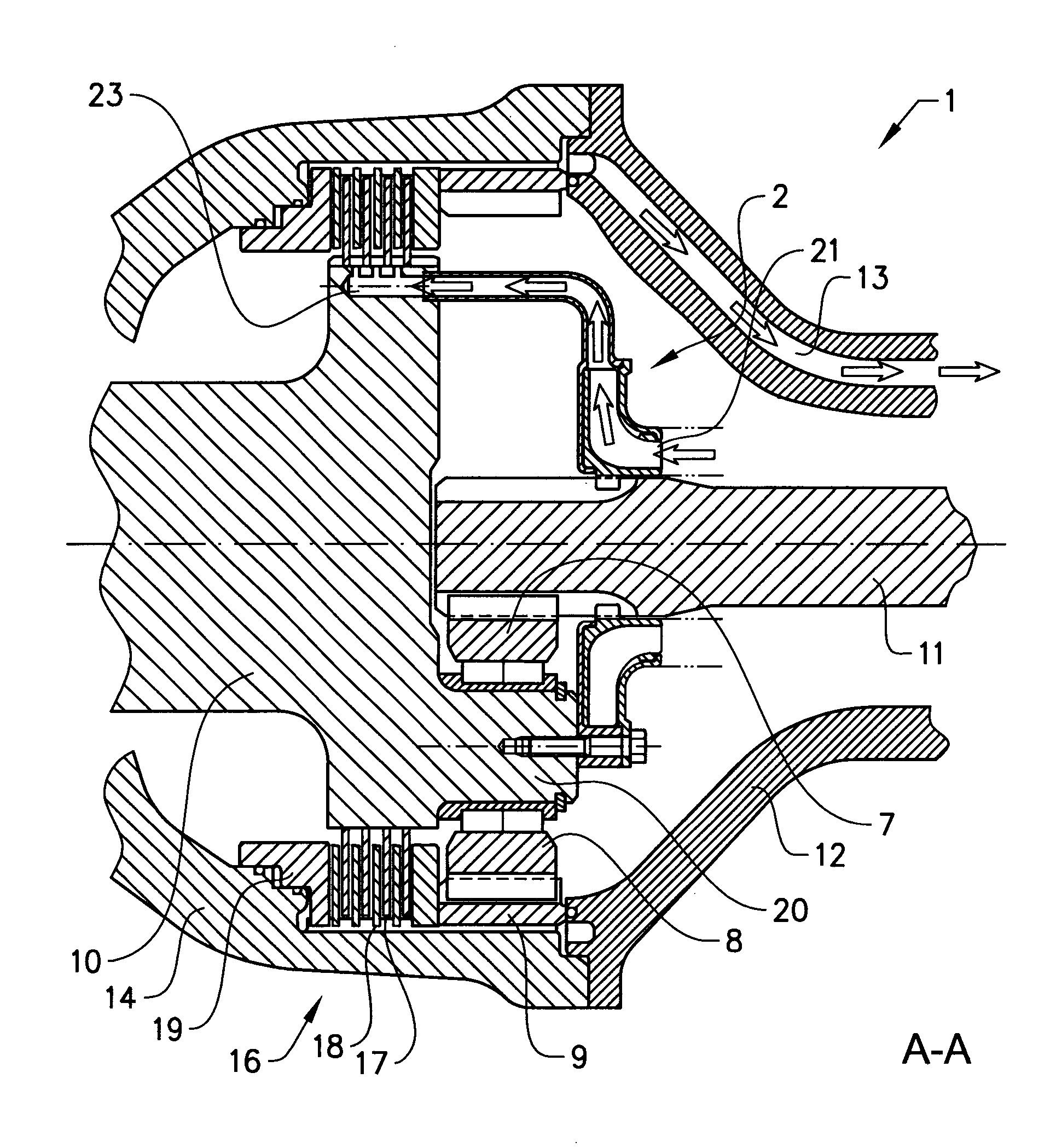
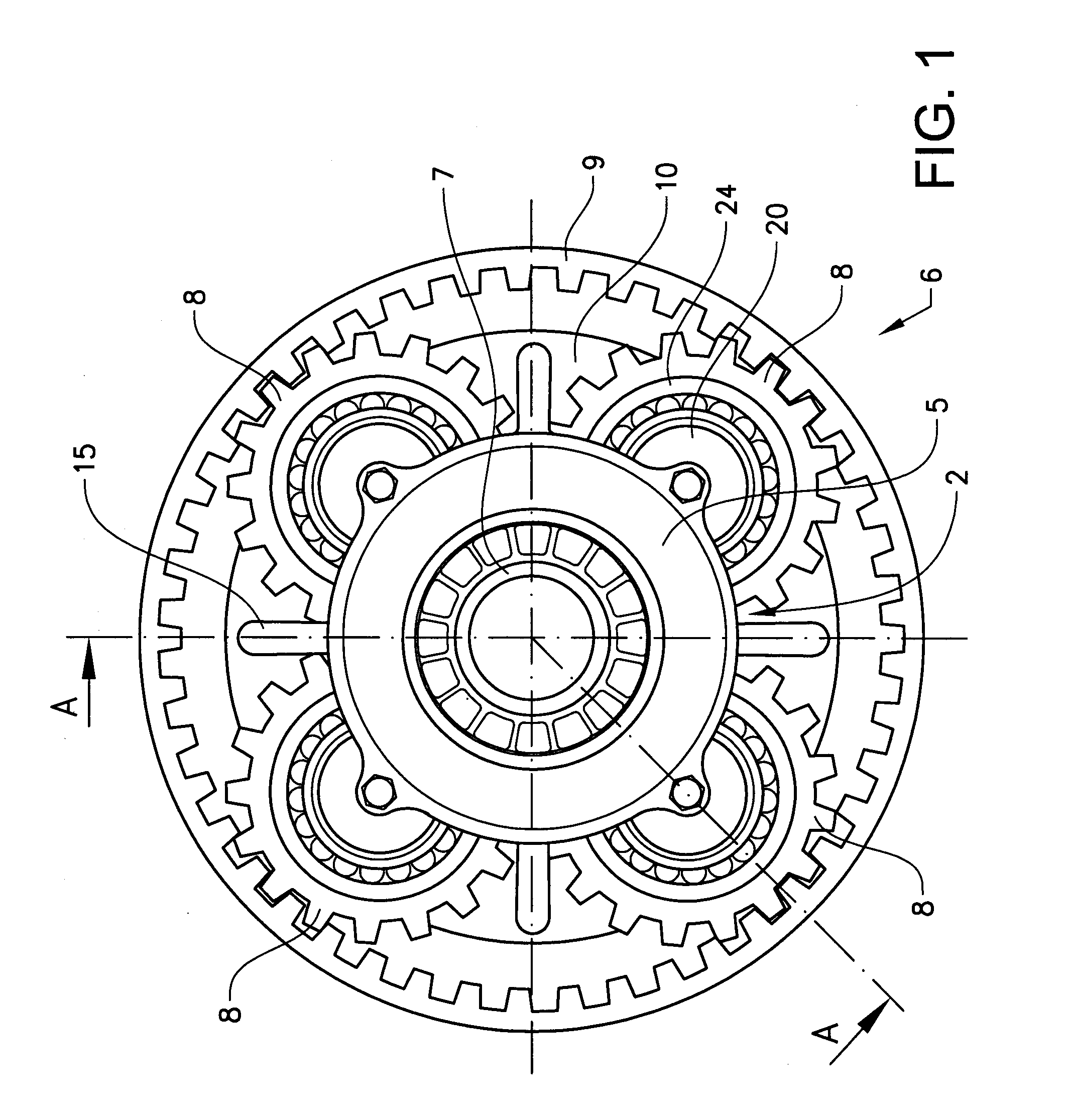
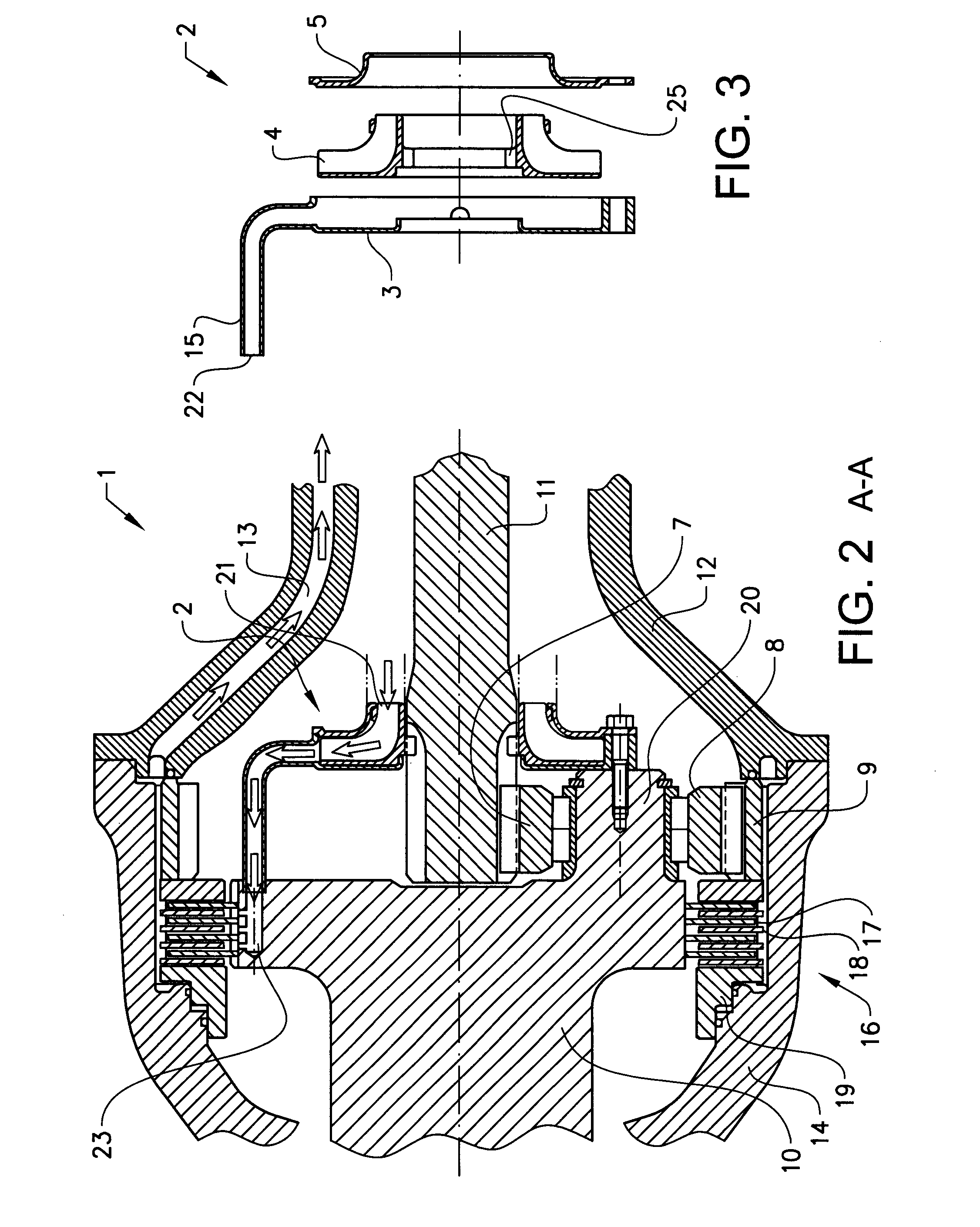
[0023]FIG. 1 shows a front view of an oil supply arrangement according to an aspect of the invention mounted on a planetary gear on a vehicle. FIG. 2 shows a split side view of the oil supply arrangement along line A-A mounted in an axle arrangement which may be part of a wheel hub. FIG. 3 shows a split view of an oil pump.

[0024]The oil pump of the oil supply arrangement is mounted on a planetary gear used as a reduction gear on a vehicle. The planetary gear is used on the vehicle to reduce the rotational speed of the incoming drive axle and at the same time to increase the rotational torque. A reduction gear of this type is often mounted in the wheel hub of a vehicle, especially on heavy vehicles used for construction, where high loads are carried at low speeds....


PUM


Abstract

An arrangement is provided for supplying oil to a brake arranged for braking an output shaft of a planetary gear. The arrangement includes a rotatable impeller for supplying oil to the brake and the impeller is arranged to be rotated by an input shaft of the planetary gear.

Description

BACKGROUND AND SUMMARY[0001]The present invention relates, according to an aspect thereof, to an arrangement for supplying oil to a brake.[0002]The invention, according to an aspect thereof, is applicable on working machines within the fields of industrial construction machines in particular wheel loaders. Although aspects of the invention will be described hereinafter with respect to a wheel loader, the invention is not restricted to this particular machine, but may also be used in other heavy working machines, such as articulated haulers, dump trucks, graders, excavators or other construction equipment.[0003]Working machines, such as articulated haulers, wheel loaders, motor graders, excavators and other construction equipments are often equipped with wet disc brakes in order to provide a sufficient brake capacity and long service intervals. A wet disc brake uses a cooling liquid, usually some kind of oil or oil emulsion, to cool the brake discs in the disc brake. The cooling liqu...

Claims


Application Information

Patent Timeline
Patent Type & Authority Patents(United States)
IPC IPC(8): F16D65/853F16D55/36F16H57/04B60T17/02E02F9/20B60K17/04
CPCF16D65/853E02F9/2083B60K17/046B60T17/02F16H57/0473F16H57/0486F16D55/36B60Y2200/411F16D2065/787F16D2125/50
Inventor ANDERSSON, THOMASAKERBLOM, MATS
Owner VOLVO CONSTR EQUIP AB
Why Eureka
Try Eureka