Motor drive configuration system and method

a configuration system and motor drive technology, applied in the field of configuration system and motor drive, can solve the problems of inability to program once the drive is commissioned, inability to configure the drive, and inability to meet the needs of the drive,

Active Publication Date: 2015-06-30
ROCKWELL AUTOMATION ASIA PACIFIC BUSINESS CTR PTE
View PDF9 Cites 2 Cited by
  • Summary
  • Abstract
  • Description
  • Claims
  • Application Information

AI Technical Summary

Problems solved by technology

One particular challenge that arises in such products is the design for various motor sizes, for facilitating programming, for sharing programming and control parameters, and so forth.
This product paradigm, however, suffers from drawbacks including limitations of installation and configuration of the drives, relatively inefficient use of control platforms between drives, in accessibility of the programming once the drive is commissioned, or, conversely, risks of access to the drives from exterior sources due to resident network connections.

Method used


Image

  • Motor drive configuration system and method
  • Motor drive configuration system and method
  • Motor drive configuration system and method

Examples


Embodiment Construction

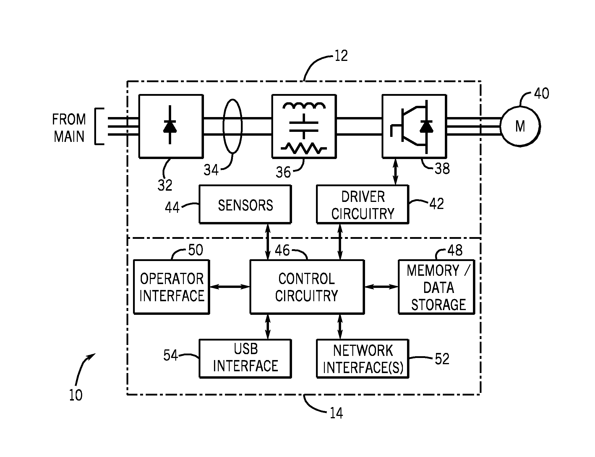
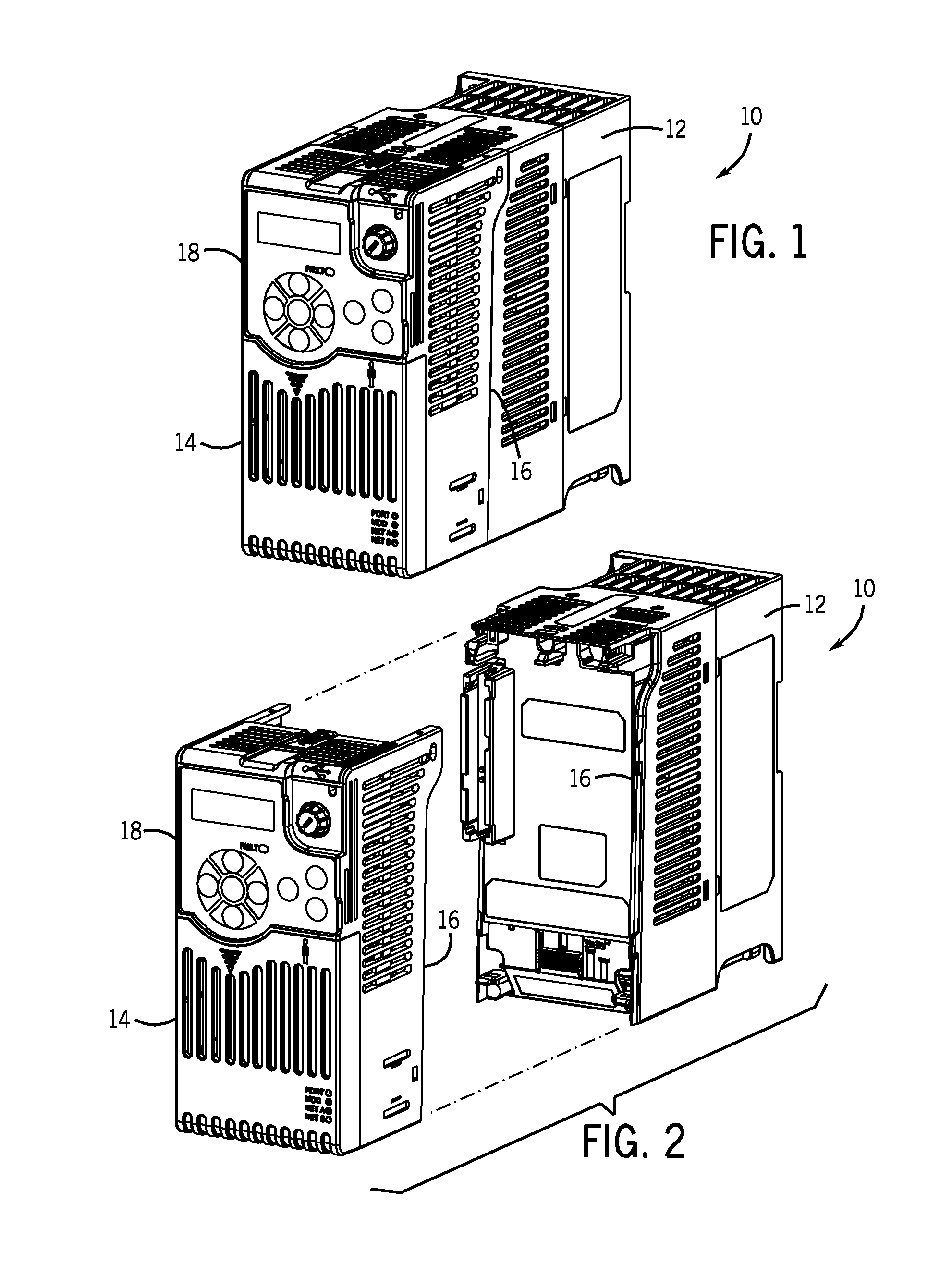
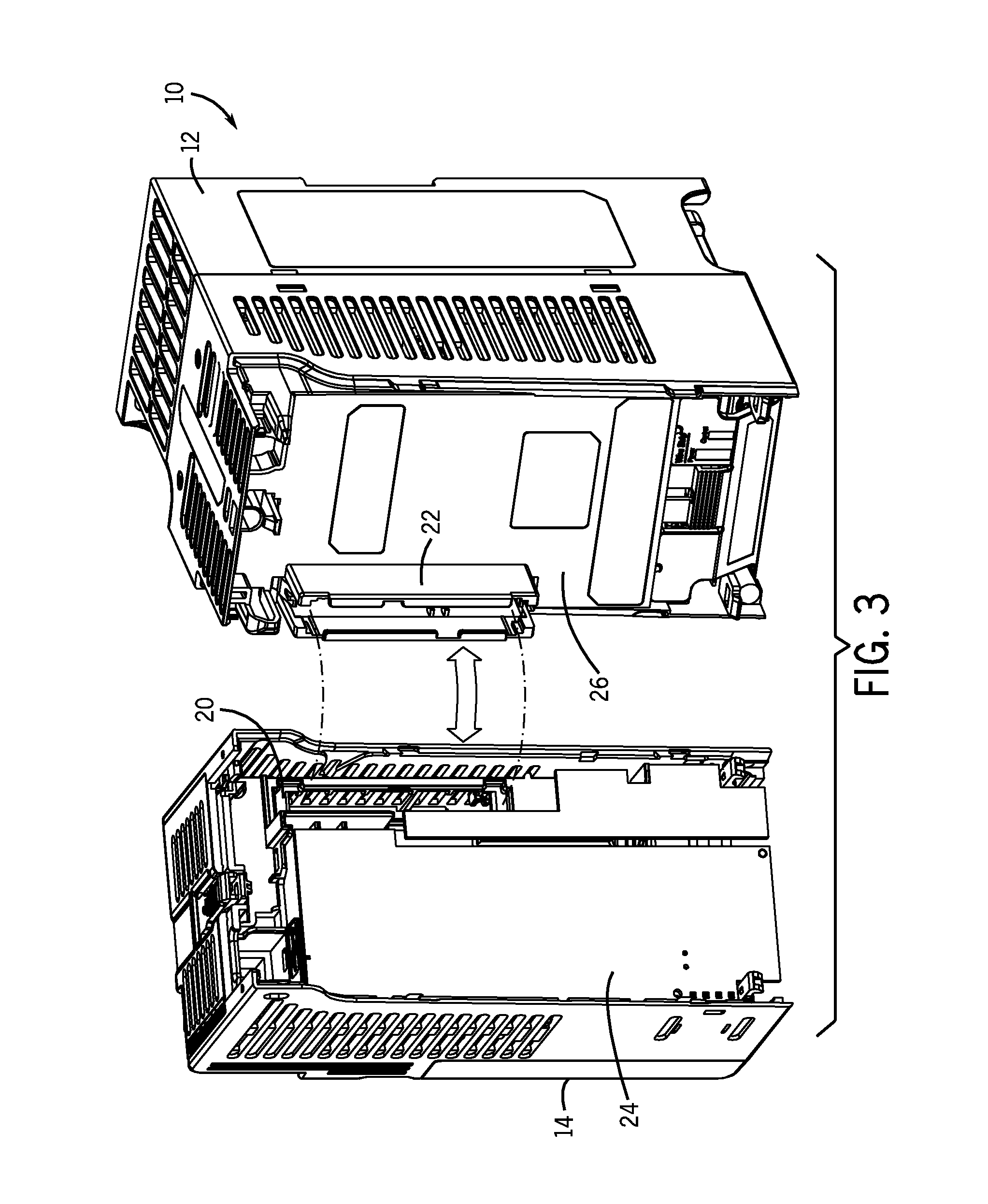
[0018]FIG. 1 illustrates an exemplary motor drive system 10 designed to power an electric motor such as an induction motor. The motor drive system essentially consists of a power sub-assembly 12 and a control sub-assembly 14 which is designed to be secured to and attached to the power sub-assembly during operation. A mechanical interface 16 allows for mating of the sub-assemblies and the control sub-assembly may be held on to the power sub-assembly in various manners, such as via snaps, fasteners, and the like. However, in a presently contemplated embodiment, the control sub-assembly and the power sub-assembly are physically configured to allow the control sub-assembly to be secured to the power sub-assembly via interfacing surfaces, such that the control sub-assembly may be attached and detached form the power sub-assembly by hand and without the use of tools. This ability to toollessly attach and detach the control sub-assembly greatly facilitates programming, reprogramming, commi...


PUM


Abstract

A motor drive comprises a power sub-assembly and a control sub-assembly removably secured to the power sub-assembly. The power sub-assembly contains all power electronic circuitry and driver circuitry for the power electronics. The control sub-assembly comprises control circuitry for implementing a motor control routine that generates control signals for the power sub-assembly. The control sub-assembly is configured to conform to a USB mass storage device class such that it will appear as an icon on a configuration station when coupled to the configuration station via a USB cable. Thereafter, the drive may be accessed by selecting the icon, and parameter file and data transfer may be performed, such as by drag-and-drop transfer steps.

Description

BACKGROUND[0001]The present invention relates generally to drive systems for powering electric motors, and more particularly to a modular drive system designed and adapted for controlling motors of various sizes and ratings.[0002]A myriad of applications exist in industry for electric motors of various types. In many applications, induction motors are driven to rotate loads, such as pumps, fans, conveyors, to mention only a few. Other types of motors may similarly be driven. A load may call for uniform speed and torque throughout its life, although many applications require much more flexible control. That is, a motor may need to be driven at different speeds and with different torques at different stages in its operation. To accommodate such needs, variable speed motor drives have been developed that allow for output waveforms of varying and controllable frequency, capable of correspondingly varying the speeds of driven motors. Similarly, equipment has been developed for soft start...

Claims


Application Information

Patent Timeline
Patent Type & Authority Patents(United States)
IPC IPC(8): H02P31/00H02P29/00
CPCH02P31/00H02P29/00G05B19/0426H02P27/04
Inventor MIDDLESTETTER, DANIELKOH, JIMMY SEE YONGMILES, SCOTTRUSTAD, JAMES
Owner ROCKWELL AUTOMATION ASIA PACIFIC BUSINESS CTR PTE
Why Eureka
Try Eureka