Rotary closure for a shoe

a technology of rotary closure and shoe, which is applied in the field of rotary closure for shoes, can solve the problems of affecting the system, the inability to meet the requirements collectively without problems, and the cost of production with relatively many parts, and achieves the effects of strong tension of the tensioning element, easy operation, and low cos

Active Publication Date: 2015-07-07
PUMA SE
View PDF28 Cites 85 Cited by
  • Summary
  • Abstract
  • Description
  • Claims
  • Application Information

AI Technical Summary

Benefits of technology

[0008]It is the object of the invention to further develop a rotary closure of the generic kind so that at the one hand an easy but also strong tension of the tensioning element is given during the closing of the rotary closure and that at the other hand an easy releasing respectively de-latching of the tensioning element is possible. Simultaneously, a light construction is aimed for and a cost-efficient production with few parts should be realized.
[0027]The rotary knob (lid) which is rotatable supported around the central axis comprises the two control elements (cams). The first control element engages in the intermediate carrier during tensioning of the wire (rotation into direction R1) and rotates the same together with the locking lever in the closing direction. A turn back of the tensioning roller is thereby prevented because the locking section (hook section) of the locking lever engages into the second blocking gearing of the tensioning roller and thus hinders the tensioning roller from turning back.
[0028]If the rotary knob (lid) is turned in the direction against the tensioning direction (direction of rotation R2) the second pawl element (cam) presses against the cam-like formed section (second crank section) of the locking lever so that the same is rotated around the swivel axis in such a manner that the locking section (hook section) is brought out of engagement with the second blocking gearing (ratchet) of the tensioning roller; now, the spooled wire can be pulled off the tensioning roller which can now rotate freely.
[0029]Beneficially, a simple design with few parts is obtained which not only keeps the production costs of the rotary closure low but also minimizes the weight of the rotary closure.
[0030]The geometrical forming of the parts, especially of the tensioning roller, allows that a high tensioning force in the tensioning element is reached with low torques at the rotary knob when the shoe respectively the tensioning element is tensioned.
[0031]However, it is possible by turning back of the rotating knob against the tensioning direction of rotation to establish a de-latched status in which the tensioning element can be drawn off from the tensioning roller.

Problems solved by technology

It is detrimental at the known systems that the mentioned requirements cannot be fulfilled collectively without problems.
Rotary closures which fulfill the mechanical requirements are often designed so complex that an expensive production with relatively many parts is given.

Method used


Image

  • Rotary closure for a shoe
  • Rotary closure for a shoe
  • Rotary closure for a shoe

Examples


Embodiment Construction

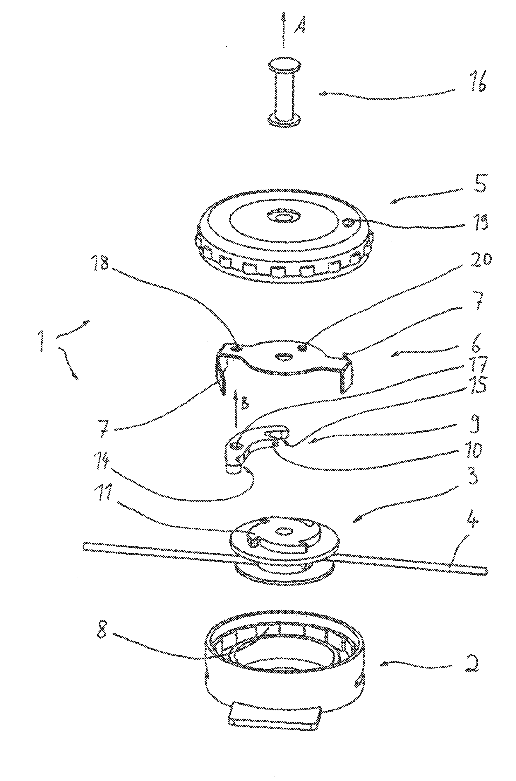
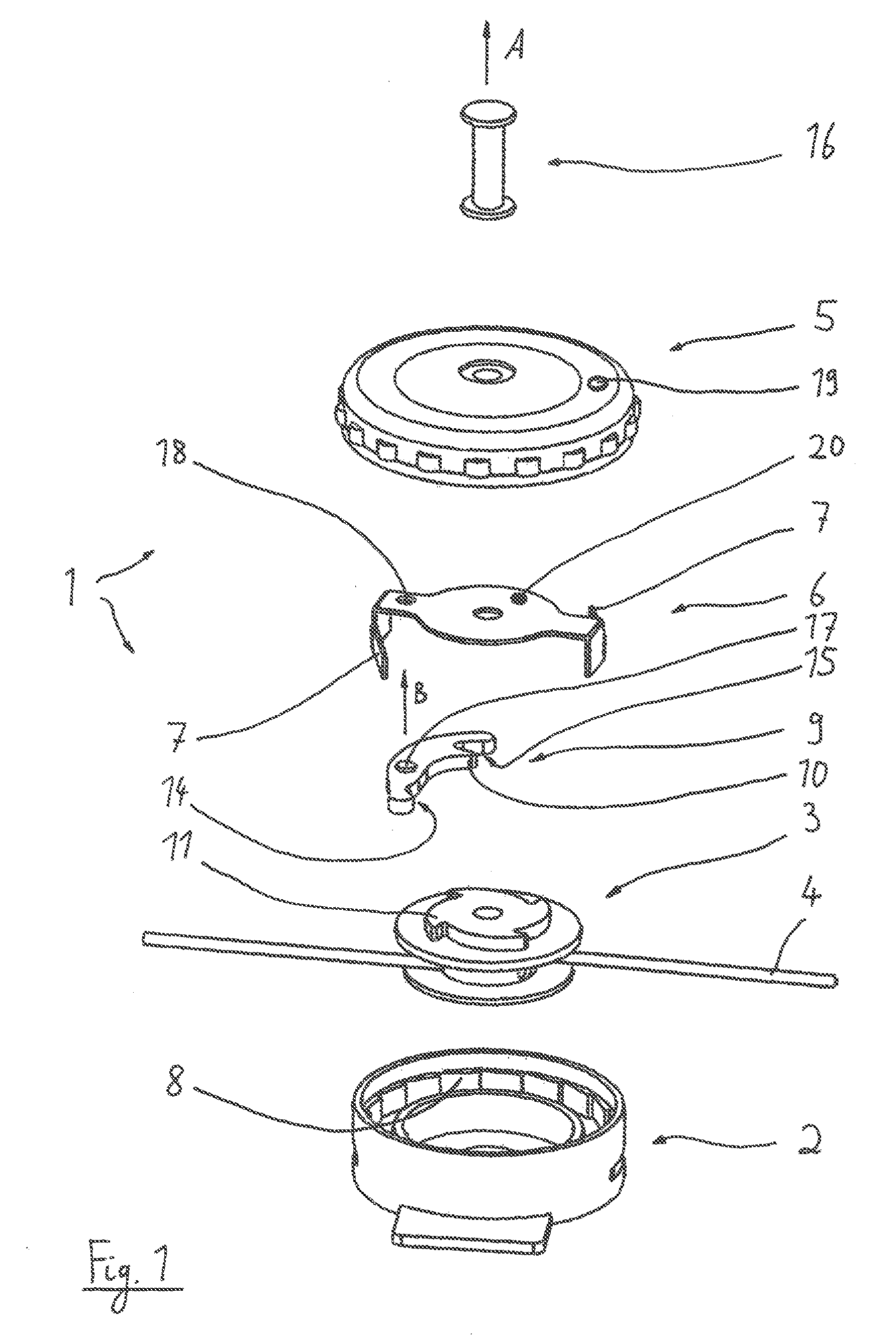
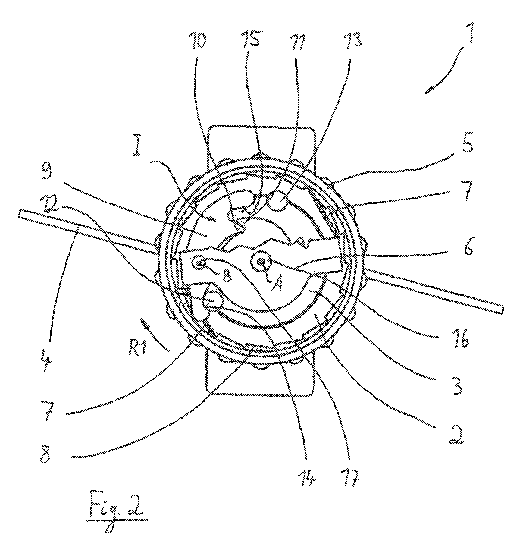
[0036]In the figures a rotary closure 1 can be seen which can be attached for example to the instep of a shoe to serve for lacing of the shoe; but also other locations for attachment are possible, for example in the lateral region or in the heel region of the shoe.

[0037]The rotary closure 1 comprises a cylindrical housing 2 which consists of plastic material and is equipped with a first blocking gearing 8 at an inner cylindrical area. By means of a bolt 16 (for example a screw with a closure in the end region by means of a screw nut) a central axis A is formed by which different rotatable parts of the rotary closure 1 are supported.

[0038]At first a tensioning roller 3 is freely rotatable supported in the housing 2. A tensioning wire respectively tensioning element 4 can be spooled on the tensioning roller 3, namely in known manner so that during spooling the shoe is tensioned respectively laced at the foot of the wearer.

[0039]At the upper side of the tensioning roller 3 a second blo...


PUM


Abstract

A rotary closure for a shoe, especially for a sports shoe, including a housing which can be attached to the shoe, a tensioning roller which is rotatably supported around an axis in the housing, wherein a tensioning element can be spooled during lacing of the shoe on the tensioning roller and a rotary knob which is arranged rotatable around the axis at the housing to turn the tensioning roller. The rotary closure furthermore includes an intermediate carrier, wherein the intermediate carrier has at least one pawl which engages in a first blocking gearing of the housing and at least one locking lever which is arranged in or at the intermediate carrier, wherein a first and a second control element which co-operate with first and second crank section of the locking lever, are disposed on the rotary knob.

Description

[0001]The present application is a 371 of International application PCT / EP2012 / 004984, filed Nov. 30, 2012, the priority of this application is hereby claimed and this application is incorporated herein by reference.BACKGROUND OF THE INVENTION[0002]The invention relates to a rotary closure for a shoe, especially for a sports shoe, comprising: a housing which can be attached to the shoe, a tensioning roller which is rotatable supported around an axis in the housing, wherein a tensioning element can be spooled during lacing of the shoe on the tensioning roller and a rotary knob which is arranged rotatable around the axis at the housing to turn the tensioning roller. Furthermore, the invention relates to a shoe with such a rotary closure.[0003]A rotary closure of the generic kind is for example known DE 297 01 491 U1. Such a rotary closure should allow the lacing of a shoe at the one hand during lacing of the tensioning element (lace thread or wire) by rotating of the rotary knob with ...

Claims


Application Information

Patent Timeline
Patent Type & Authority Patents(United States)
IPC IPC(8): A43C11/16A43C11/20A43C11/00
CPCA43C11/16A43C11/165Y10T24/2183Y10T24/2187Y10T24/3724A43C11/20A43C11/004Y10T24/3713
Inventor JUNGKIND, ROLAND
Owner PUMA SE
Why Eureka
Try Eureka