Pneumatic actuator for impact engraving tool

a pneumatic actuator and engraving tool technology, applied in the field of impact type handheld engraving tools, can solve the problems that the pneumatic impact engraving tool used by jewelers lacks sufficient striking force at slow speeds, and achieves the effects of increasing the striking force per pulse, improving the striking effect, and improving the control

Active Publication Date: 2015-07-14
GRABOUTIL
View PDF17 Cites 15 Cited by
  • Summary
  • Abstract
  • Description
  • Claims
  • Application Information

AI Technical Summary

Benefits of technology

[0007]I have invented a pneumatic piston actuator for a pneumatic impact tool, especially useful for engraving jewelry, firearms, knives and other fine workpieces, but possibly having other uses as well. My piston actuator is able to pulse at a relatively slow rate, with increased striking force per pulse, and gives an engraver more control.
[0010]An air inlet at the rear of the pneumatic chamber supplies the rear of the piston base with forward driving pressure, and an equalizing vent at a forward end of the chamber reduces the effect of pressure and vacuum on the operation of the spring return means throughout the stroke.
[0013]In a further form the graver assembly is rotationally adjustable in the tool body, allowing the user to customize grip and graver position relative to the air supply line connected to the tool body.
[0015]In a further form, the graver assembly includes a slotted sleeve secured to the tool body and a graver tip secured to the slotted sleeve with a spring-loaded ball detent. The ball detent allows the graver tip limited motion relative to the tool when struck by the piston assembly. In a further form, the graver assembly is axially adjustable with an external threaded collar engaging mating threads on the sleeve.

Problems solved by technology

In my experience, prior pneumatic impact engraving tools used by jewelers tend lack sufficient striking force at slow speeds, possibly due to their relatively fast oscillation rate and light strikers.

Method used


Image

  • Pneumatic actuator for impact engraving tool
  • Pneumatic actuator for impact engraving tool
  • Pneumatic actuator for impact engraving tool

Examples


Embodiment Construction

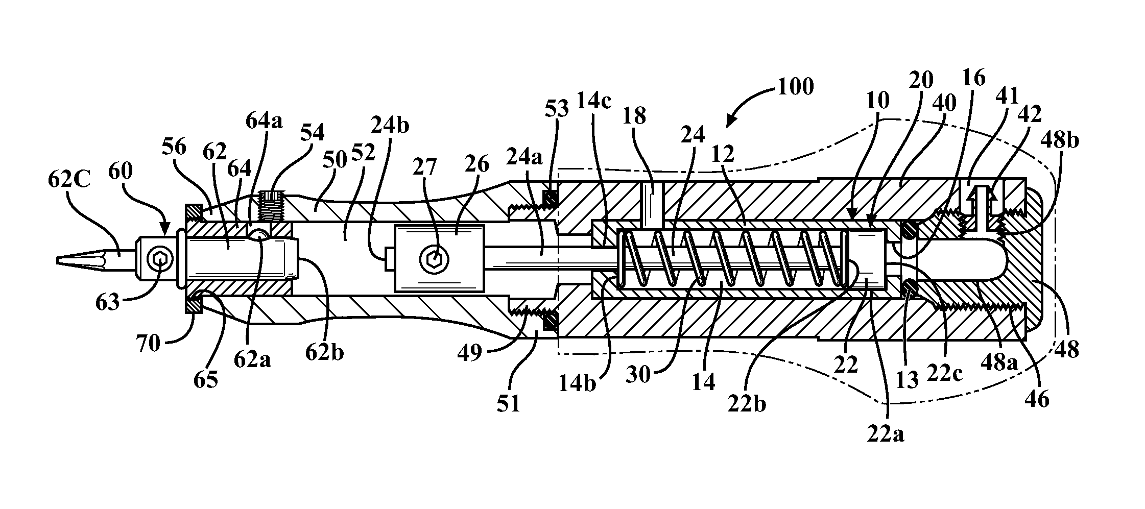
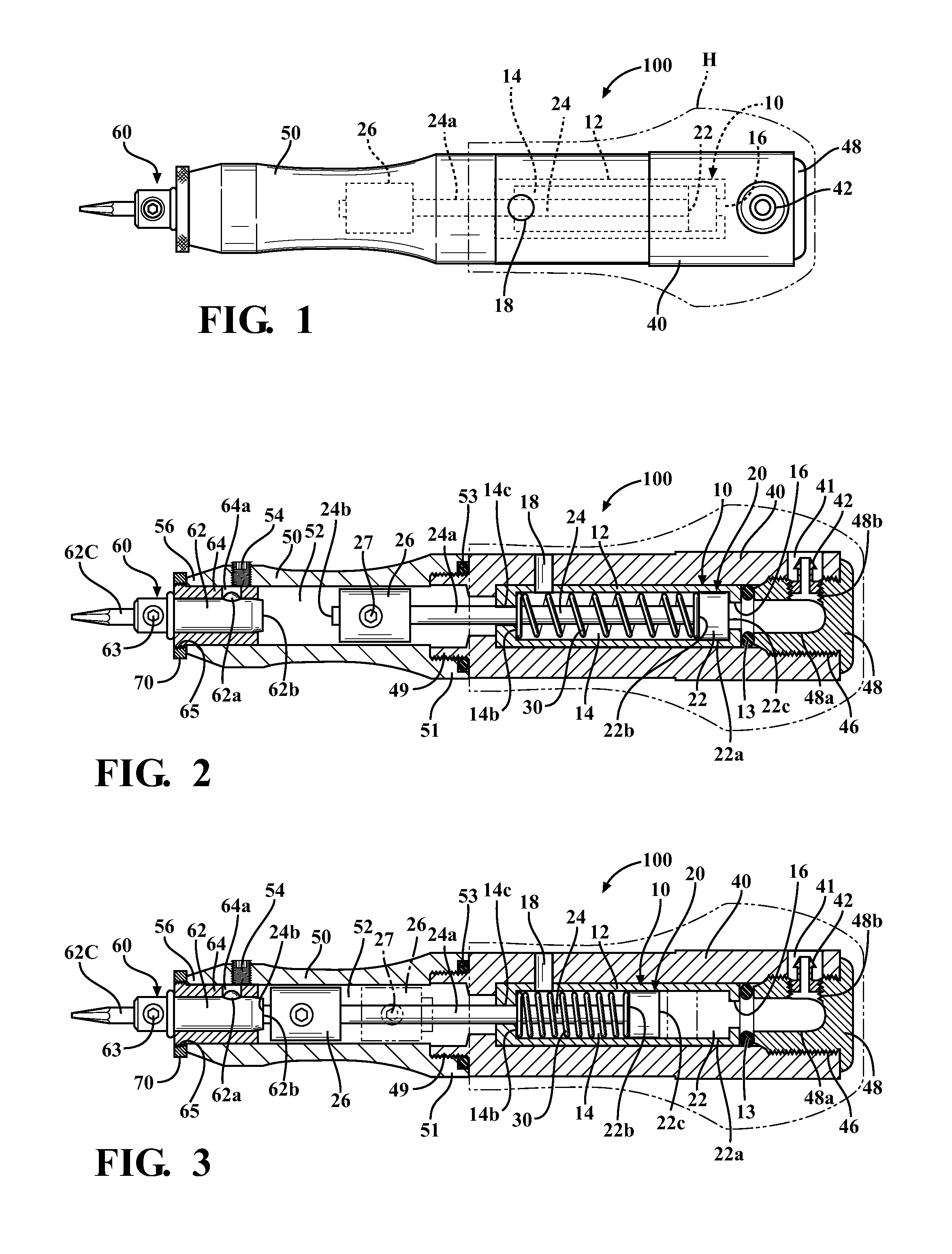
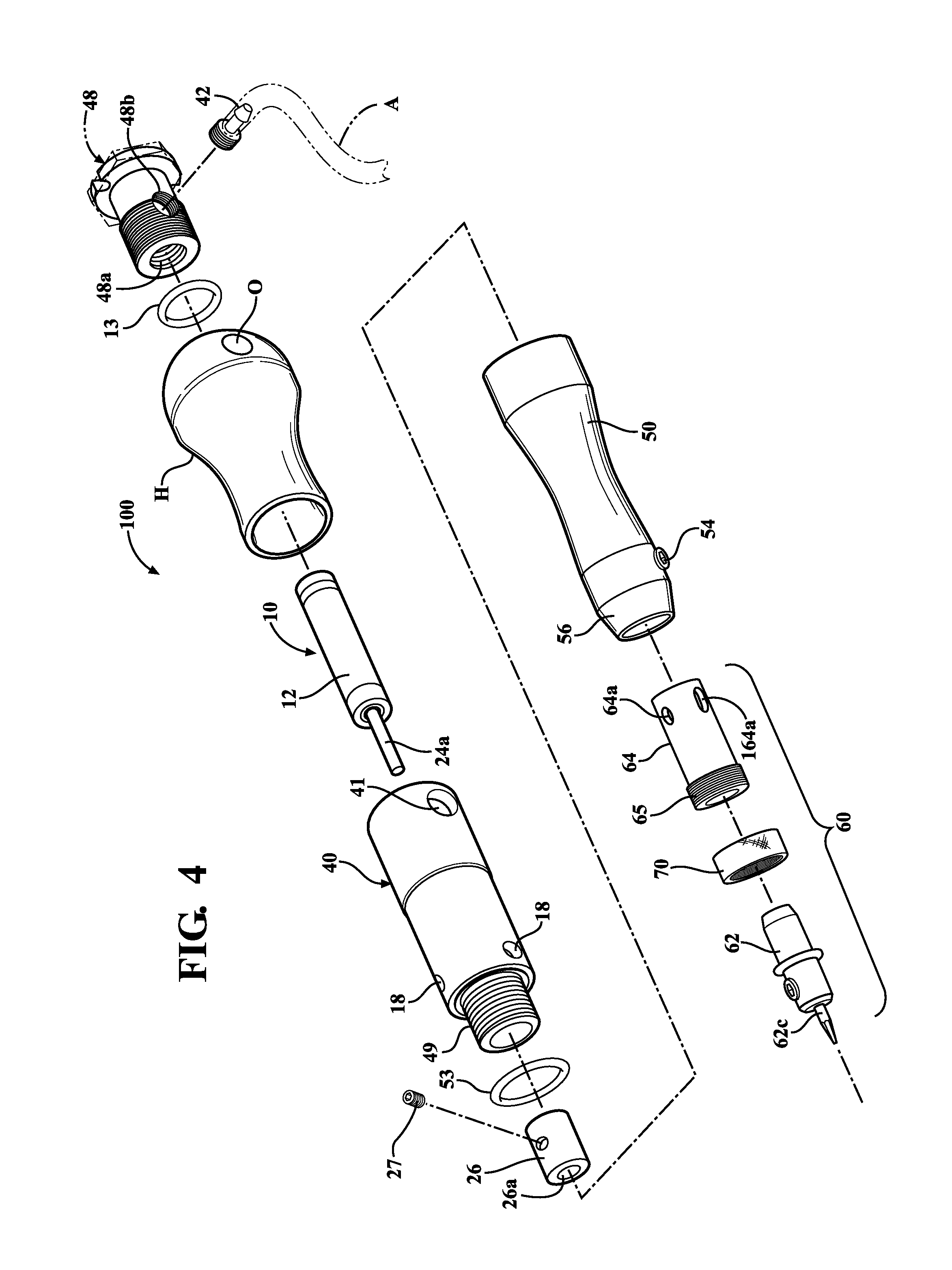
[0024]Referring first to FIGS. 1 and 2, a pneumatic tool 100 with a pneumatic actuator 10 is shown in exemplary form in order to teach how to make and use the claimed invention. Actuator 10 has a pneumatic cylinder body 12 with an internal pneumatic chamber 14. An air supply port 16 is located at or near a rear end of chamber 14, adapted to be connected to or in communication with a pressurized air supply from a pneumatic air source. An optional handgrip H for fitting over the tool body is shown in phantom.

[0025]A piston assembly 20 is mounted for sliding, reciprocal movement in chamber 14 in response to pulses of pressurized air from port 16. Piston assembly 20 includes a rear piston base 22 located toward the rear end of chamber 14, a striker pin portion 24 extending forwardly from the piston base 22, and an external striker head 26. Piston base 22 has a shape and diameter approximating the cross-section of chamber 14 (in the illustrated example, circular), and preferably has a sl...


PUM


Abstract

A pneumatic actuator for use in pneumatic impact tools of the type used to engrave jewelry, and an impact tool adapted for the pneumatic actuator. The actuator includes a cylinder body with a pneumatic chamber housing a piston assembly reciprocating in response to pulses of pressurized air. The piston assembly includes a piston base and a striker pin in the pneumatic chamber, an outer end of the striker pin extending through and residing outside a forward end of the chamber. The outer end of the striker pin has an enlarged striker head of greater mass than the striker pin and / or the piston base in the chamber. A pneumatic impact tool is also disclosed, and includes a forward stylus section having a guide bore for the striker head and holding a graver assembly in spaced relationship to the striker head.

Description

RELATED APPLICATIONS / PRIORITY BENEFIT CLAIM[0001]None.FIELD[0002]The subject matter of the present application is in the field of impact-type handheld engraving tools, often used by jewelers.BACKGROUND[0003]Handheld pneumatic impact tools are commonly used for engraving or removing small amounts of material from jewelry and other fine workpieces, and may even be used in orthopedic and dental surgery. Such tools typically use a pneumatically-driven piston reciprocating in a pneumatic chamber in the tool handle to transmit force to a fixed anvil in contact with a graver tip. The force transmitted to the graver tip through the anvil removes material from the workpiece. Air pressure is supplied from a separate controller through a flexible supply line. Different types of controller are commercially available.[0004]The piston is driven intermittently by air pressure against a return spring to strike the anvil and transmit impact force to the graver in pulses. Since the graver tip is usua...

Claims


Application Information

Patent Timeline
Patent Type & Authority Patents(United States)
IPC IPC(8): B24B23/02B25D9/14B24B23/04B25D9/00
CPCB25D9/14B24B23/02B25D17/08B25D9/04B25D9/08B25D2250/371B44B11/02
Inventor DECAMILLIS, CHRISTIAN
Owner GRABOUTIL
Why Eureka
Try Eureka