Bicycle having an electrical auiliary drive

a technology of electrical auiliary drive and bicycle, which is applied in the direction of electric vehicles, electric devices, human/animal propulsion, etc., can solve the problem of substantial increase in design expenditure of additional step-down transmissions

Inactive Publication Date: 2015-07-14
INTERHOLZ HANDELS
View PDF13 Cites 6 Cited by
  • Summary
  • Abstract
  • Description
  • Claims
  • Application Information

AI Technical Summary

Benefits of technology

[0007]The invention is therefore based on the object of implementing an electrical auxiliary drive for a bicycle such that, on the one hand, a pedaling frequency for the pedal

Problems solved by technology

These difficulties can be avoided by an automatic transmission, but an automatic transmission also cannot take influence on the operating point of the wheel hub motor r

Method used


Image

  • Bicycle having an electrical auiliary drive
  • Bicycle having an electrical auiliary drive

Examples


Embodiment Construction

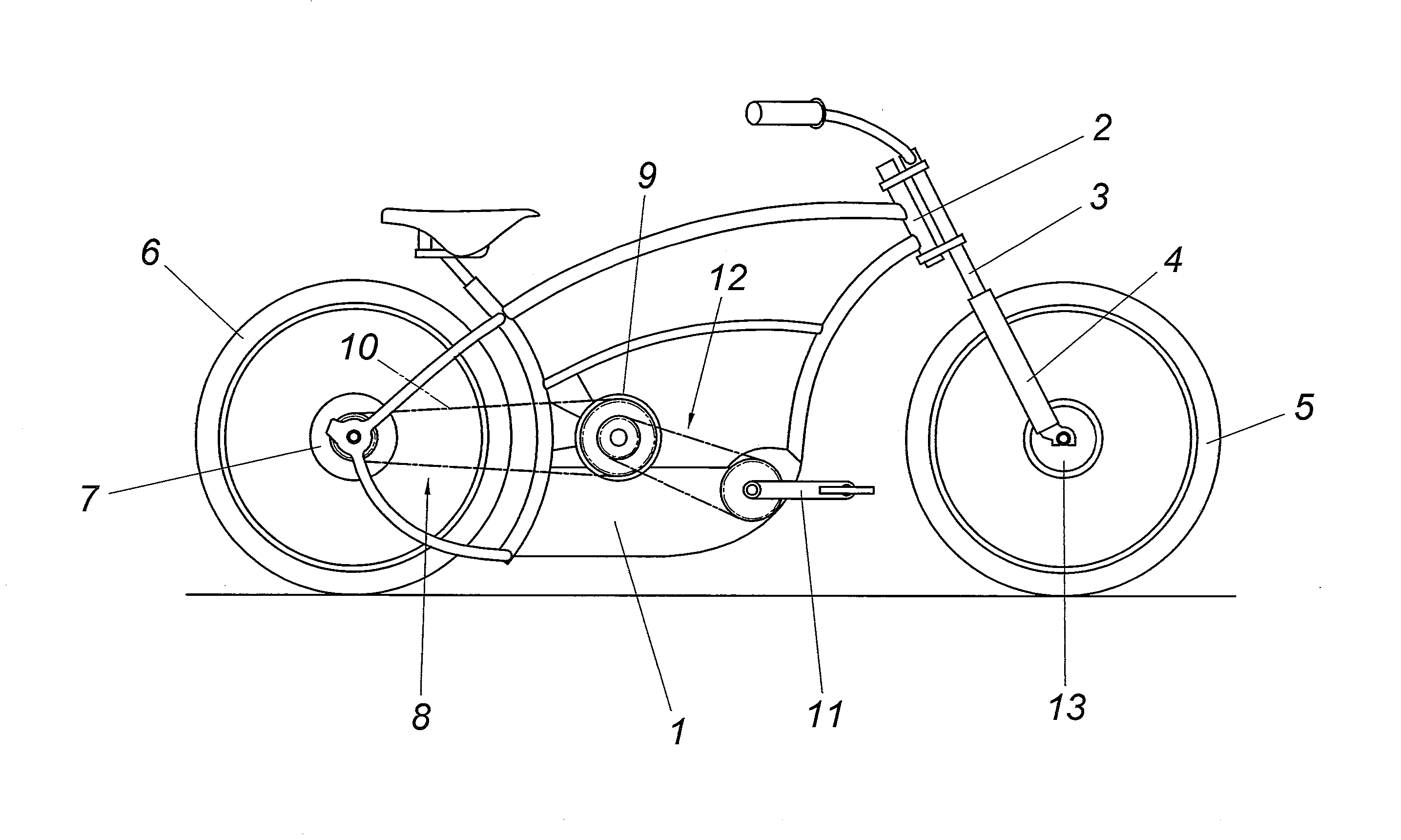
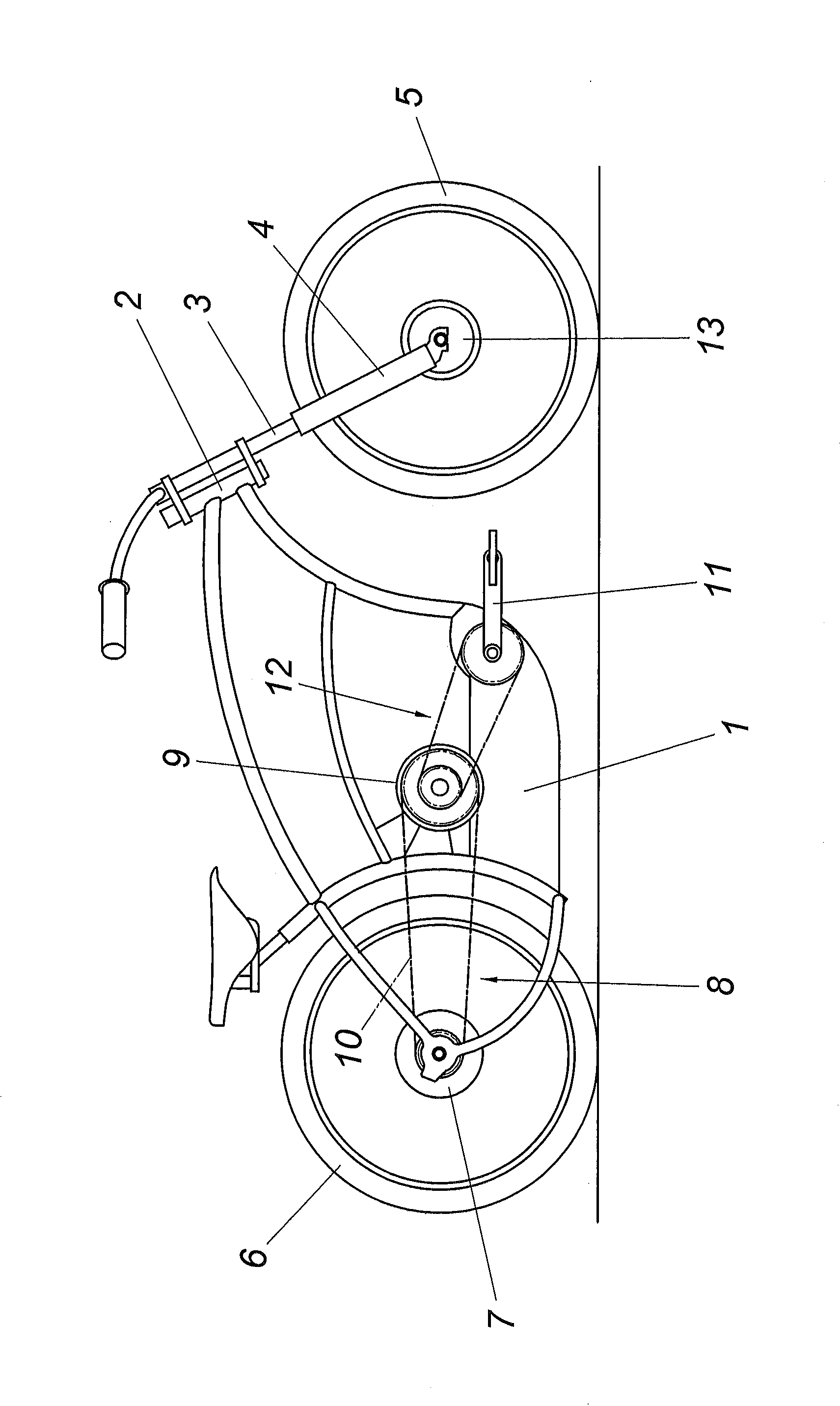
[0012]The bicycle shown has a frame 1 having a mount 2 for a steering column 3, which carries a mounting fork 4 for a front wheel 5. The rear wheel 6, which is mounted in the frame 1, is provided with a wheel hub motor 7, on which the spokes of the rear wheel 6 engage, which is not shown for reasons of comprehensibility, however. The wheel hub motor 7 is connected via a transmission gearing 8 to an auxiliary motor 9 of identical size, which is supported on the frame 1, wherein the transmission gearing 8, which is implemented as a revolving traction drive 10 having a chain or a toothed belt as the traction means, engages on the freewheel hub of the wheel hub motor 7. The pedal crank 11 of the pedal crank drive 12, which is mounted in the frame 1, has a drive connection to the freewheel hub of the auxiliary motor 9 via a revolving traction means. However, it is also possible to assign the auxiliary motor 9 to the pedal crank mount, so that a revolving traction means between the pedal ...


PUM


Abstract

A bicycle having a pedal crank drive (12) and having an electrical auxiliary drive, which is connected to the pedal crank drive (12), is described, which has a wheel hub motor (7) having a freewheel hub for the rear wheel (6). To provide advantageous drive conditions, it is proposed that the wheel hub motor (7) for the rear wheel (6) have a drive connection via a transmission gearing (8) to an electrical auxiliary motor (9) of identical size.

Description

CROSS REFERENCE TO RELATED APPLICATIONS[0001]Applicant claims priority under 35 U.S.C. §119 of Austrian Application No. A50112 / 2013 filed on Feb. 19, 2013, the disclosure of which is incorporated by reference.BACKGROUND OF THE INVENTION[0002]1. Field of the Invention[0003]The invention relates to a bicycle having a pedal crank drive and having an electrical auxiliary drive, which is connected to the pedal crank drive, and which has a wheel hub motor having a freewheel hub for the rear wheel.[0004]2. Description of the Related Art[0005]To provide advantageous design conditions for electrical auxiliary drives in bicycles, providing a wheel hub motor for the rear wheel, whose spokes engage directly on the wheel hub motor, is known. The pedal crank drive is connected to the freewheel hub of this wheel hub motor, wherein typically a shift transmission is interposed, to be able to provide an advantageous pedaling frequency range for a comparatively large speed range for the pedal crank. T...

Claims


Application Information

Patent Timeline
IPC IPC(8): B60K1/00B62M6/55B62M6/40B62M6/65
CPCB62M6/55B62M6/40B62M6/65B60L2200/12B60L2220/44B60L2240/12B60L2240/421B60L50/20Y02T10/64
Inventor STIEGER, EWALD
Owner INTERHOLZ HANDELS
Why Eureka
Try Eureka