System for increasing controllability for an aircraft

a controllable and aircraft technology, applied in the field of aircraft design, can solve the problems of aircraft operational costs, aircraft weight and aerodynamic drag reduction, etc., and achieve the effect of reducing the design size of the horizontal tail plane (htp) of the aircraft, reducing the weight and aerodynamic drag of the aircraft, and reducing the weight of the aircra

Inactive Publication Date: 2015-07-14
AIRBUS OPERATIONS SL
View PDF18 Cites 0 Cited by
  • Summary
  • Abstract
  • Description
  • Claims
  • Application Information

AI Technical Summary

Benefits of technology

[0002]The technical problem addressed in the invention is to provide a system that lets the design size of the Horizontal Tail Plane (HTP) of an aircraft to be reduced. Thus reducing the weight and the aerodynamic drag of the aircraft and, as a consequence, the aircraft operational costs.
[0006]In simple terms, HTP influence on aircraft longitudinal stability depends on the centre of gravity of the aircraft (c.g.), which is variable during aircraft operation and on a coefficient that characterises the HTP size that is known as the HTP volume. The further away the c.g. is located from the HTP and the larger the HTP is, it results in greater aircraft longitudinal stability.
[0010]The technical problem addressed by this invention is directed to reduce the size of an adjustable HTP in aircraft designs limited by controllability, in other words, with a minimum HTP size determined by longitudinal stability criteria. The invention thus provides a system to increase aircraft controllability, which, in turn, provides an increase in the HTP lift coefficient, allowing a reduction of HTP size and of total aircraft weight, thus contributing the advantage of reduced aircraft operating costs.PRIOR ART OF THE INVENTION
[0016]Additionally, in order to overcome the mentioned drawbacks in the technical field, this invention seeks the following technical effects:
[0019]The first technical effect enables the invention system constitution to be simplified and in particular, to eliminate the need of installing actuators or motors for the high-lift device deflection.
[0020]The second technical effect enables adequate high-lift device deflection to be produced in order to increase the HTP lift coefficient in absolute value, depending on the various HTP angles of attack, without any detriment in lift and drag at other angles of attack values.

Problems solved by technology

Thus reducing the weight and the aerodynamic drag of the aircraft and, as a consequence, the aircraft operational costs.

Method used


Image

  • System for increasing controllability for an aircraft
  • System for increasing controllability for an aircraft
  • System for increasing controllability for an aircraft

Examples


Embodiment Construction

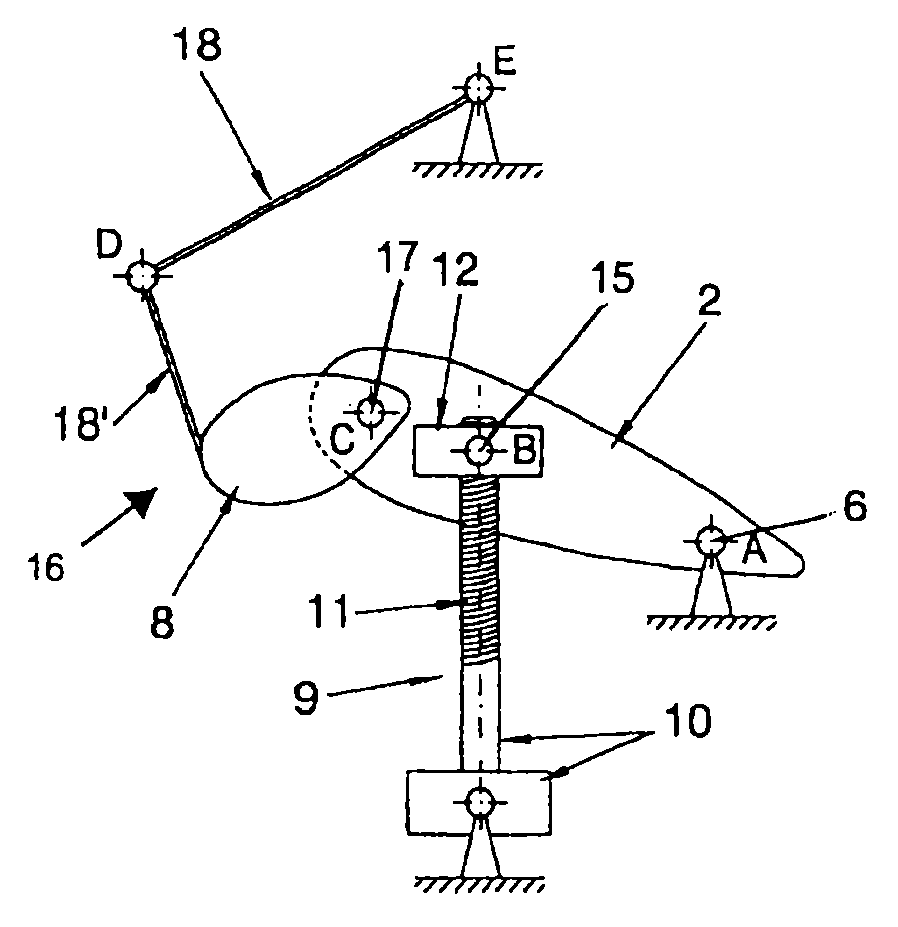
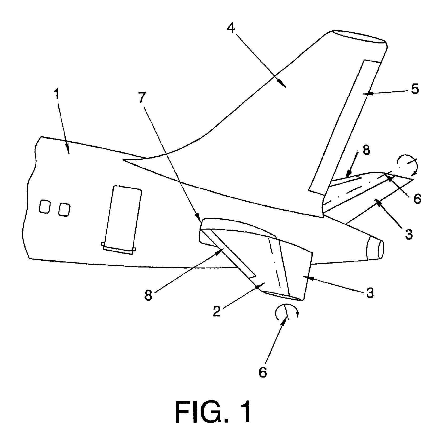
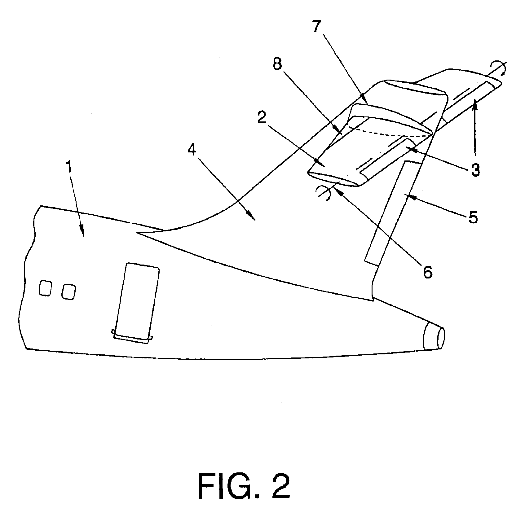
[0015]In order to solve the technical problem addressed, the invention incorporates movable high-lift devices installed in the HTP, with the function of increasing the HTP lift coefficient.

[0016]Additionally, in order to overcome the mentioned drawbacks in the technical field, this invention seeks the following technical effects:[0017]First: to take advantage of HTP tilting movement in order to transmit it to the deflection movement of an HPT high-lift device;[0018]Second: to provide an increase in the HTP lift coefficient in a selective way over the full range of HTP angle of attack values, in particular for HTP stall values.

[0019]The first technical effect enables the invention system constitution to be simplified and in particular, to eliminate the need of installing actuators or motors for the high-lift device deflection.

[0020]The second technical effect enables adequate high-lift device deflection to be produced in order to increase the HTP lift coefficient in absolute value, d...


PUM


Abstract

The system includes deflection transmission means (16) to provide a deflection position of the high-lift device (8) for each setting angle position of an adjustable HTP (2). Preferably, the deflection transmission means (18,20,23) comprise essentially of a mechanical linkage connected between the high-lift device (8) and the aircraft (1).

Description

FIELD OF THE INVENTION[0001]This invention relates to the aeronautical industry, more particularly to the field of aircraft design, being intended for its implementation in the horizontal tail plane of an aircraft.OBJECT OF THE INVENTION[0002]The technical problem addressed in the invention is to provide a system that lets the design size of the Horizontal Tail Plane (HTP) of an aircraft to be reduced. Thus reducing the weight and the aerodynamic drag of the aircraft and, as a consequence, the aircraft operational costs.[0003]The invention is intended for an aircraft that incorporates an “adjustable HTP”, which is conventional in commercial aircraft. Adjustable HTPs incorporate a “trim system” for providing a tilting movement for the entire HTP at a given angle (“setting angle”) with respect to the aircraft, producing a change in the HTP angle of attack. The trim system function is to automatically provide “longitudinal” balance to the aircraft, i.e. without any need for pilot inter...

Claims


Application Information

Patent Timeline
Patent Type & Authority Patents(United States)
IPC IPC(8): B64C9/10B64C5/02
CPCB64C9/10B64C5/02Y02T50/32Y02T50/44Y02T50/30Y02T50/40
Inventor VELA ORGE, PILARNAMER, ARNAUDPASCUAL FUERTES, ANGELSIMON CALERO, FRANCISCO JAVIER
Owner AIRBUS OPERATIONS SL
Why Eureka
Try Eureka