
Holding mechanism for display device and assembling method of the same

a technology of holding mechanism and display device, which is applied in the direction of electric apparatus casing/cabinet/drawer, instruments, horology, etc., can solve the problems of easy handling of the reverse side of the front cover member, difficult deformation of the elastic member, etc., to prevent the appearance of the protruding part externally, reduce the protruding part, and facilitate handling

Active Publication Date: 2015-07-14
CALSONIC KANSEI CORP
View PDF11 Cites 0 Cited by
  • Summary
  • Abstract
  • Description
  • Claims
  • Application Information

AI Technical Summary

Benefits of technology

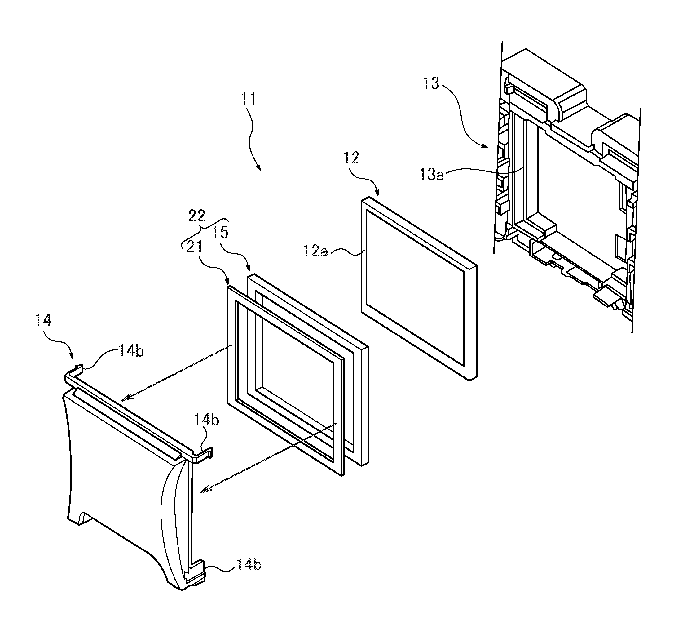
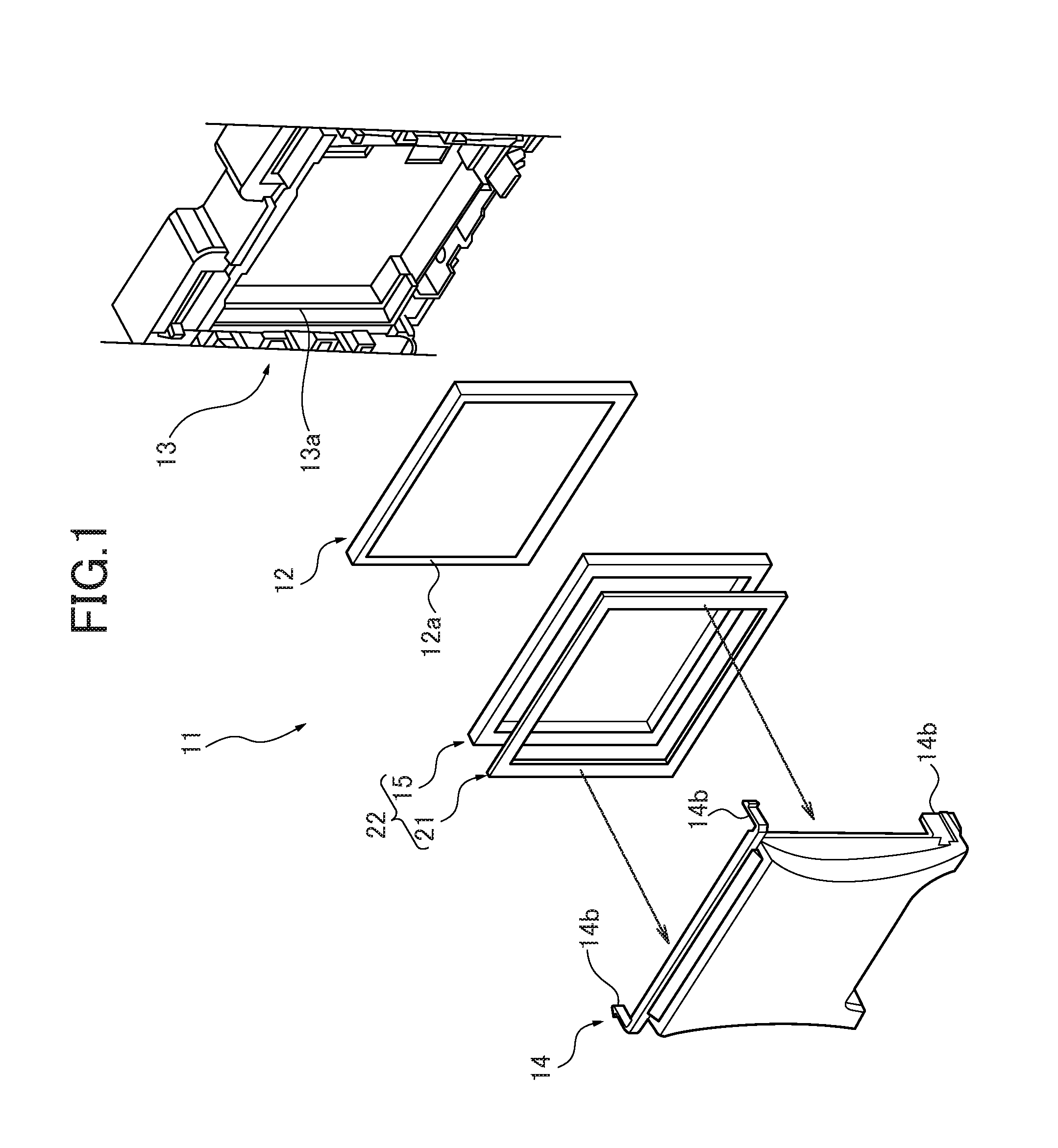
[0020]According to the foregoing configuration, the following advantageous effects can be obtained. That is to say, since the thin plate-like member having shape retention is attached to the elastic member on the side facing the front cover member, the elastic member becomes difficult to deform and easy to handle to adhere on the reverse side of the front cover member. Therefore, the incidence of a position gap is decreased when adhering the elastic member to the reverse side of the front cover member, and the need for re-adhering can be reduced. As a result, unsightly appearance by damage of the elastic member due to the re-adhering and an exposure of the glue side for adhering the elastic member can be prevented.
[0021]Further, the elastic member is homogeneously-squeezed over a wide range pressed through the thin plate-like member since it is pressed via the thin plate-like member when the front cover member is attached to a front side of the display device. As a result, protruding of the elastic member can be reduced. Thus, unsightly appearance due to the protruding part being visible externally can be prevented.
[0022]In addition, the elastic member is homogeneously-squeezed via the thin plate-like member over a wide range, when the elastic member is held by a reinforcing rib provided to at least a part of the front cover member in order to make lighter the front cover member. As a result, the elastic member is prevented from being linearly-squeezed only at the part pressed by the reinforcing rib and its surrounding part is raised. Moreover, the holding effect by an equable pressure can be obtained.
[0023]According to this invention described in another embodiment of the present invention, the following functional effects will be obtained. That is to say, since the surface of the thin plate-like member having shape retention is antireflection-finished, the presence of the thin plate-like member can be unobtrusive externally. Further, it can be prevented that the reflected light from the thin plate-like member makes the display difficult to see and stands out in comparison with the display of the display device by the antireflection-finishing of the surface of the thin plate-like member.
[0024]According to this invention described in still another embodiment of the present invention, the following functional effects will be obtained. That is to say, the thin plate-like member becomes easier to handle and its workability can be improved by making the thin plate-like member at least partly larger than the elastic member in shape. Further, the elastic member can be made less visible by the thin plate-like member.

Problems solved by technology

That is to say, since the thin plate-like member having shape retention is attached to the elastic member on the side facing the front cover member, the elastic member becomes difficult to deform and easy to handle to adhere on the reverse side of the front cover member.

Method used


Image

  • Holding mechanism for display device and assembling method of the same
  • Holding mechanism for display device and assembling method of the same
  • Holding mechanism for display device and assembling method of the same

Examples


supplement example 1

[0051]Note that, for the thin plate-like member 21 described above, a resin plate, metal plate, and so on, may be used. In this case, the thin plate-like member 21 is assumed to be a resin plate. The thin plate-like member 21 is preferably a dark color such as black. When the thin plate-like member 21 is assumed to be a resin plate, it is preferable that the thin plate-like member 21 have a thickness of approximately 0.3 mm to 1 mm in order to have shape retention. If the thin plate-like member 21 is thinner than 0.3 mm, it cannot maintain the shape retention. And, if the thin plate-like member 21 is thicker than 1 mm, it cannot be attached since the thin plate-like member 21 becomes thicker than the gap between the display device 12 and the front cover member 14. The thin plate-like member 21 is assumed to be a frame shape surrounding the rim of the surface of the display device 12 (for instance, the frame-like member 12a).

[0052]Then, a compound packing (a frame-shaped packing) 22 ...

supplement example 2

[0055]Here, for instance, the antireflective finishing (the antireflective-finished part 24) can be a surface texturing, matte finish (fine concavo-convex processing), and so on.

Configuration 3

[0056]The thin plate-like member 21 having shape retention is made at least partly larger than the elastic member 15 in shape (slightly uneven part 25).

supplement example 3

[0057]A part (compound packing 22) consisting of the elastic member 15 and the thin plate-like member 21 is preferably produced by punching into a frame shape a compound sheet which is made of the elastic member 15 and the thin plate-like member 21 adhered together and integrated in advance.

[0058]Then, while the elastic member 15 is kept inflated laterally by compressing the compound sheet with high pressure, the compound sheet is punched from the side of the thin plate-like member 21 and released from the pressure. Therefore, the compound packing 22 wherein the shape of the thin plate-like member 21 is slightly larger than the elastic member 15 can be obtained in a single process.

[0059]Note that, to obtain the compound packing 22 wherein the thin plate-like member 21 is entirely larger than the elastic member 15, the compound sheet shall be punched while compressing the whole part supposed to be the compound packing 22. On the other hand, to obtain the compound packing 22 wherein t...


PUM

PropertyMeasurementUnit
thicknessaaaaaaaaaa
shapeaaaaaaaaaa
shape retentionaaaaaaaaaa

Abstract

A holding mechanism for a display device has a front cover member attached to a surface of a housing containing the display device so as to cover the display device, and an elastic member arranged between the display device and a front cover member. A thin plate-like member having shape retention is attached to the elastic member on a side facing the front cover member, and the elastic member attached to the thin plate-like member is attached to an internal side of the front cover member to prevent an unsightly appearance and to make the adherence of the elastic member to the surface of the display device easier.

Description

CROSS-REFERENCE TO RELATED APPLICATIONS[0001]The present application is based on and claims priority from Japanese Patent Application Number 2012-110327, filed on May 14, 2012, the disclosure of which is hereby incorporated by reference herein in its entirety.BACKGROUND OF THE INVENTION[0002]1. Field of the Invention[0003]The present invention relates to a holding mechanism for a display device used for an indicator, a navigator and so on, and an assembling method of the holding mechanism for a display device.[0004]2. Description of the Related Art[0005]A vehicle such as an automobile has an instrument panel installed at a front portion in a vehicle interior. A controller of an air-conditioner is installed at the center in the width direction of the instrument panel. Some of these controllers of an air-conditioner have a display device.[0006]FIGS. 8 to 10 illustrate a controller 1 of an air-conditioner having a conventional display device.[0007]The controller 1 shown in FIGS. 8 to 1...

Claims


Application Information

Patent Timeline
Patent Type & Authority Patents(United States)
IPC IPC(8): G02F1/1333H05K13/00B60K35/00G04G17/04F21V1/00F21V21/00F21V7/04G06F1/16
CPCG06F1/1601B60K35/00G02F1/133308G04G17/045H05K13/00B60K2350/00B60K2350/2082B60K2350/2086B60K2350/941G02F2001/13332G02F2201/503G02F2201/505Y10T29/49002B60K2370/00B60K2370/39B60K2370/81B60K2370/693G02F1/13332
Inventor KAMEDA, MITSUAKI
Owner CALSONIC KANSEI CORP
Learn More