Fluid pump having at least one impeller blade and a support device

a technology of fluid pump and impeller blade, which is applied in the field of mechanical engineering, can solve problems such as unsatisfactory objectives, and achieve the effect of good pumping capacity in operation

Active Publication Date: 2015-07-28
ECP ENTWICKLUNGSGMBH
View PDF181 Cites 62 Cited by
  • Summary
  • Abstract
  • Description
  • Claims
  • Application Information

AI Technical Summary

Benefits of technology

[0009]This object has previously not been ideally achieved in the prior art. It is therefore the underlying object of the present invention to further develop a pump of the described type

Problems solved by technology

This object has previously not been

Method used


Image

  • Fluid pump having at least one impeller blade and a support device
  • Fluid pump having at least one impeller blade and a support device
  • Fluid pump having at least one impeller blade and a support device

Examples


Embodiment Construction

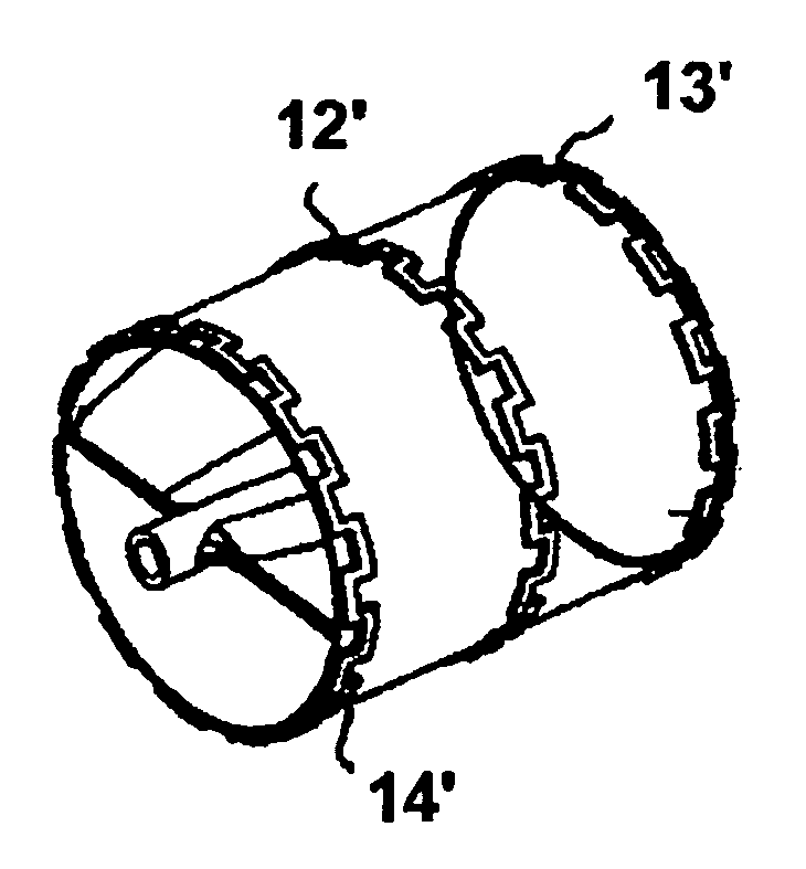
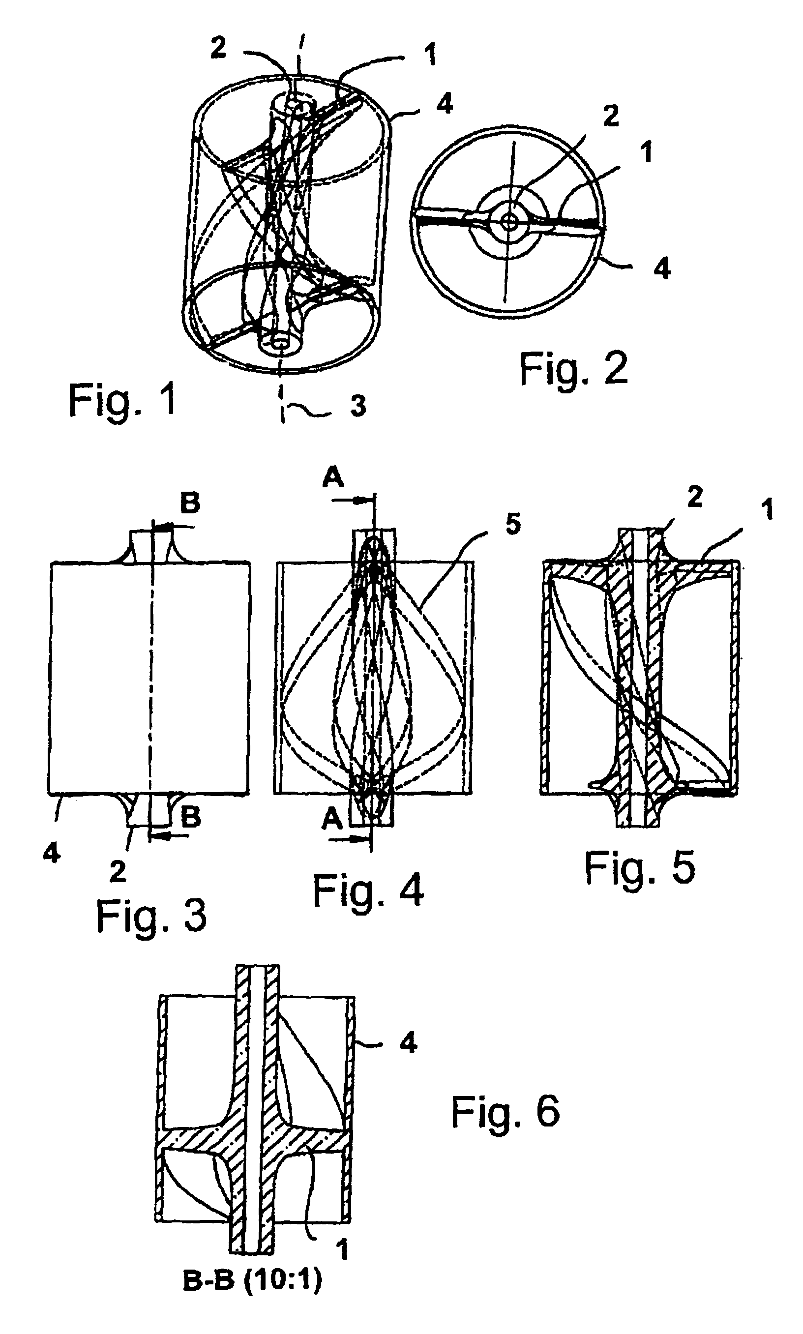
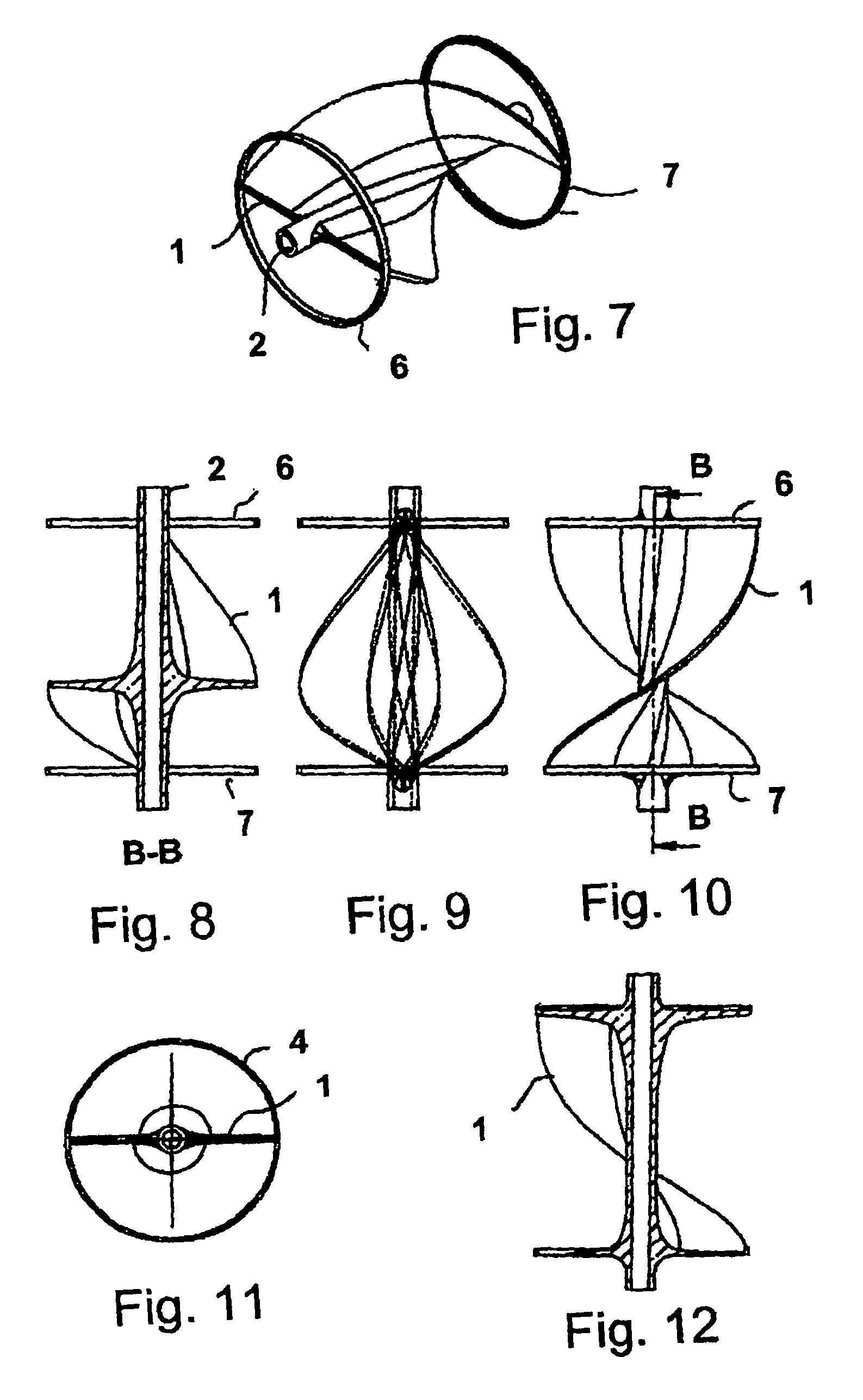
[0060]FIG. 1 shows, in a three-dimensional view, a rotor of a fluid pump, in particular of a micropump, for the axial conveying of blood, such as is typically used in medicine to assist the human heart. Such a pump is, for example, mounted at the end of a hollow catheter and conducts blood under pressure from a chamber of the heart into a blood vessel when it is introduced into a heart ventricle through a blood vessel. For this purpose, a rotor rotates at some thousand revolutions per minute to achieve the required conveying capacity. The impeller blade 1 is helical in form, is connected to a neck 2 in the region of the axis of rotation 3 and is supported outwardly by a support device 4 in the form of a tubular sleeve, to which the impeller blade 1 is connected at its outer margin.

[0061]The neck 2 is typically connected to a drivable shaft which extends through the hollow catheter and blood vessel to a motor drive which can typically be arranged outside the body. A sluice is provide...


PUM


Abstract

A fluid pump has at least one impeller blade which is rotatable about an axis of rotation and conveys a fluid in operation. The fluid pump has a support device which supports the at least one impeller blade in at least one support region. The support device is changeable between a first state in which the at least one impeller blade is radially compressed and a second state in which the at least one impeller is radially expanded. The at least one impeller blade extends at least partly radially inwardly with respect to the axis of rotation from the at least one support region in the radially expanded state of the blade.

Description

BACKGROUND OF THE INVENTION[0001]The invention is in the field of mechanical engineering, in particular micromechanics, and addresses fluid pumps which work with rotating impeller blades and are particularly configured for use in areas which are difficult to access.[0002]Pumps of this type can be used, for example, in the medical field and can also have particularly small construction shapes for this purpose.[0003]A special application of micropumps is, for example, the assistance for the pump force of the human heart. Pumps used in this area are usually introduced into the body through blood vessels and are optionally operated in a chamber of the heart.[0004]A plurality of such pumps have already become known which have different constructional shapes. An axial flow pump has become known, from WO 98 / 53864, and equally from EP 1 738 783 A1, which in each case has a rotor in the form of a rigid shaft, said rotor being provided with impeller blades and said shaft being outwardly journ...

Claims


Application Information

Patent Timeline
IPC IPC(8): F04D29/18A61M5/142A61M1/10A61M60/13A61M60/237A61M60/416A61M60/806A61M60/808A61M60/825
CPCA61M1/101A61M1/1024A61M5/14236F04D29/181A61M2205/0244A61M2205/0266A61M60/414A61M60/148A61M60/808A61M60/237A61M60/416A61M60/13A61M60/806A61M60/825F04D19/00F04D29/528
Inventor SCHUMACHER, JOERGROEHN, DANIEL
Owner ECP ENTWICKLUNGSGMBH
Why Eureka
Try Eureka