Single and multiple use applicator for volatile fluids having a protective device for guarding against being cut by glass shards formed within the applicator

a technology of glass shards and applicators, which is applied in the field of single and multiple use applicators for volatile fluids, can solve the problems of difficult if not impossible to effectively control and vary the amount of fluid metered, and the device is limited to the size, so as to facilitate effective metering of fluid, facilitate effective metering, and facilitate the effect of control

Active Publication Date: 2015-07-28
FRAZIER THOMAS G
View PDF27 Cites 10 Cited by
  • Summary
  • Abstract
  • Description
  • Claims
  • Application Information

AI Technical Summary

Benefits of technology

[0004]It is an object of the invention to provide an applicator that effectively provides for multiple applications of volatile fluid from the applicator to surfaces over time (e.g., over the course of a week or more), by providing a cap that effectively guards against the applicator tip from drying out and / or that guards against the fluid undergoing a premature, unintended, and / or undesired chemical reaction, such as one triggered by being exposed to the atmosphere.
[0005]Another object of the invention to provide an applicator that minimizes the chances of a user of the applicator being injured by a glass shard, created when a glass ampoule positioned in the applicator and containing the fluid to be dispensed from the applicator and applied by the applicator to a surface is crushed to release the fluid from the ampoule, penetrating through the tube and cutting the user's forefinger and / or thumb when the user squeezes the tube inwardly using his forefinger and thumb to cause the fluid released from the ampoule to flow to the applicator tip and be meter out from the applicator tip onto a surface.
[0008]The pen-like design of my invention is an improvement in the art, providing a more ergonomic solution to problems encountered by single and multi-use applicators in the applicator field, as well as providing a more cost efficient applicator.
[0009]Further, my invention allows for the use of softer, more pliable resins than those typically used for prior art applicators to be used in manufacturing my applicator, making “activation” (that is, squeezing inwardly to cause the glass ampoule to be crushed) of my new applicator easier. In contrast to my inventive applicator, the use of such softer resins in prior art applicators that use wing-like pairs of gripping members or an extended breaking lever results in non-performance of the wing-like pair of gripping members and the extended breaking lever to activate the applicator, that is, to break the glass ampoule positioned in the applicator. Moreover, the use of more pliable resins in the tube and the dispensing member of my invention, as opposed to the rigid resins typically used for prior art applicators, facilitates effective metering of fluid out from my applicator to a surface. The use of soft pliable resins for the tube and dispensing member of my invention results in a tube and a dispensing member that are pliable to the extent that the tube and dispensing member of the invention are very responsive to the force placed on them by the user squeezing the protective device between the user's forefinger and thumb such that the amount of fluid dispensed from my applicator may be easily controlled by how much force the user creates squeezing the protective device between his forefinger and thumb. The ability to easily control and vary the flow rate of fluid being metered out from prior art applicators is hindered due to being constructed of rigid resins, which results in applicators that are hard to squeeze to meter out fluid therefrom. If the user only wishes that a small amount of fluid be dispensed from my applicator, the user only needs to squeeze the protective device lightly, until the desired amount of fluid is dispensed from my applicator where upon the squeezing of my applicator may be stopped, and if the user wishes to create a larger flow of fluid from my dispenser, he need only squeeze my applicator harder at the protective device to cause a larger flow of fluid from my applicator until the desired amount of fluid is dispensed from my applicator where upon the squeezing of my applicator may be stopped. The flow of fluid from my applicator may be varied by merely varying the amount “squeeze” force applied to my applicator by the user squeezing my applicator at the protective device, a light squeeze creating a low flow rate of fluid from my applicator and a more forceful squeeze creating a high flow rate of fluid from my applicator.

Problems solved by technology

Depending on the physical attributes of the tube, occasionally a glass shard from the crushed ampoule may penetrate through the tube, causing injury to the user of the applicator by cutting into the user's finger and / or thumb, when the user subsequently squeezes the tube inwardly, after the fluid contained in the ampoule is released from the ampoule due to the ampoule being crushed, to cause the fluid released from the ampoule to flow to the applicator tip and be metered out from the applicator tip onto a surface.
However, such devices have shortcomings, such as being cumbersome to use and non-ergonomic, in part due to such devices requiring that the tubes be constructed using rigid resins to permit the use of wing-like pairs of gripping members or the use of an extended breaking lever to effectively crush the ampoule, such rigid resin construction of the tubes making it difficult if not impossible to effectively control and vary the amount of fluid metered out from the applicator onto a surface by squeezing the tubes.
Further, such devices are limited to the size and shape of the specific ampoule to be used that must match the internal confines of the device.
To accommodate larger or smaller fills (that is, larger ampoules having larger amounts of fluid or smaller ampoules having smaller amounts of fluids), for example, a whole new device must be made, increasing the costs of tooling in an injected molded applicator shell.
Another shortcoming of such devices is that they do not effectively provide for multiple applications of volatile fluids over time.
That is, such devices do not effectively provide for multiple applications of volatile fluids over an extended period of time, such as a week or more, by failing to prevent drying out of the applicator tips and / or by failing to prevent the fluid from undertaking an unintended chemical reaction due to atmospheric exposure of the fluid on their daubers.

Method used


Image

  • Single and multiple use applicator for volatile fluids having a protective device for guarding against being cut by glass shards formed within the applicator
  • Single and multiple use applicator for volatile fluids having a protective device for guarding against being cut by glass shards formed within the applicator
  • Single and multiple use applicator for volatile fluids having a protective device for guarding against being cut by glass shards formed within the applicator

Examples


second embodiment

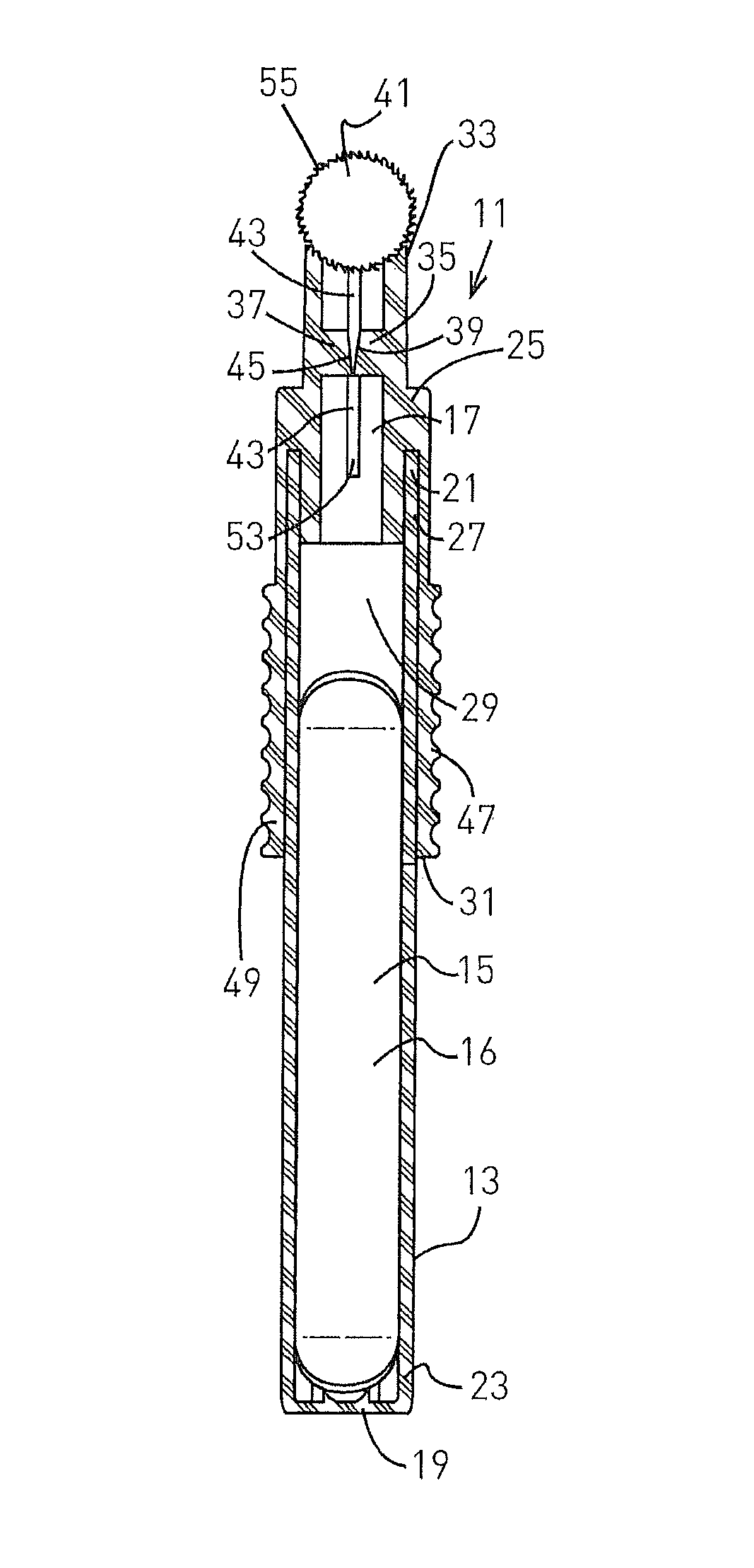
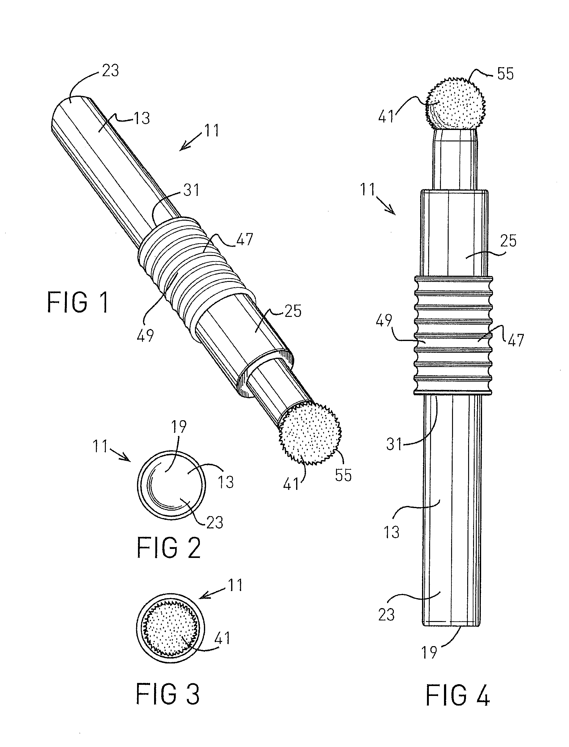
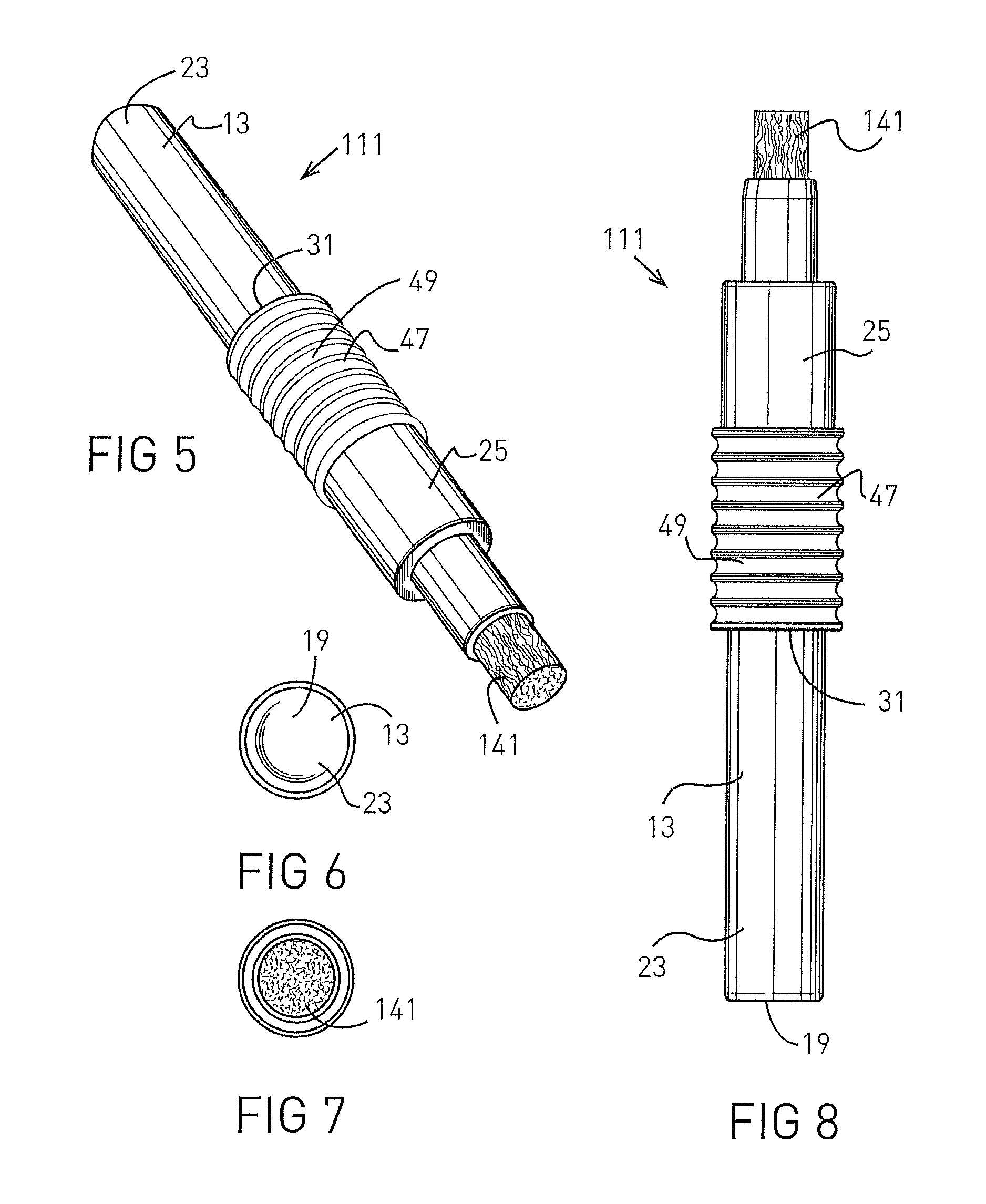
[0054]Turning now to FIGS. 5-8, 19, and 22-24, there is shown the invention. Here, the inventive applicator 111 is substantially the same as the applicator 11, except that a cylindrical dauber 141 is used in the applicator 111 rather than the dauber 41 and needle-like member 43 used in the applicator 11. Preferably, the cylindrical dauber 141 comprises a plurality of fiber strands, in side by side relation forming a porous cylindrical structure. The fiber strands are of any suitable synthetic material, such as polyester fiber, compatible with the fluid 16 to be carried and dispensed from the applicator 111. The dauber 141 preferably is mounted on the second end 33 of the dispensing member 25 by press-fitting a portion of the dauber 141 into the passageway 29 at the second end 33 of the dispensing member 25 so that a portion of the dauber 141 protrudes from the passageway 29. Also, an adhesive may be applied between a portion of dauber 141 and the portion of the dispensing member 25 ...

third embodiment

[0057]Turning now to FIGS. 9-12, 20, and 22-24, there is shown the invention. Here, the inventive applicator 211 is substantially the same as the applicator 111, except that a dauber 241 is used in the applicator 211 rather than the dauber 141 used in the applicator 111. Preferably, the dauber 241 is the same as the dauber 141, except the end portion 257 of the dauber 241 flares radially outwardly as shown in the drawings. The structure of dauber 241 is described in detail in my U.S. Pat. No. 7,004,657, which is hereby incorporated herein by reference. The dauber 241 is mounted on the applicator 211 in the same manner that the dauber 141 is mounted on the applicator 111. The applicator 211 operates in substantially the same manner as the applicator 111.

fourth embodiment

[0058]Turning now to FIGS. 13-17, 21, and 22-26, there is shown the invention. Here, the invention applicator 311 is substantially the same as the applicator 111, except that a dauber 341 is used in the applicator 311 rather than the dauber 141 used in the applicator 111, and a dauber holding device 359 is used in the applicator 311 for holding the dauber 341 and for mounting the dauber 341 onto the dispensing member 25 of the applicator 311. In this embodiment of the invention, the dauber 341 is substantially a larger version of the dauber 141, which preferably is mounted onto the dauber holding device 359 by being press-fit into an trough-like shaped or up-side-down saddle shaped portion 361 of the dauber holding device 359. An adhesive also may be used between the dauber 341 and the portion 361 of the dauber holding device 359 to hold the dauber 341 in place. The dauber holding device 359 also has a cylindrical hollow tube portion 363 that is integral with and extends away from t...


PUM


Abstract

The inventive applicator has a pliable plastic tube for holding a hermetically sealed crushable glass ampoule containing fluid to be dispensed from the applicator and applied by the applicator to a surface, and a pliable dispensing member mounted onto the plastic tube. The dispensing member has a dauber from which the fluid is dispensed and a protective device which surrounds a portion of the tube and is squeezed inwardly between the user's forefinger and thumb to cause the portion of the tube positioned thereunder to deform inwardly and crush the crushable glass ampoule positioned within the tube to release the fluid contained within the ampoule. The protective device guards against and minimizes the chances of users being cut by glass shards of the crushed glass ampoule when the protective device is subsequently squeezed inwardly to cause the fluid to move through the applicator to the dauber.

Description

FIELD OF THE INVENTION[0001]This invention relates to applicators for dispensing fluid therefrom and applying said fluid to a surface, and more particularly concerns applicators, such as the applicators of Frazier U.S. Pat. Nos. 7,004,657 and 6,254,297, both of which are hereby incorporated herein by reference, having a hermetically sealed crushable glass ampoule, which contains the fluid to be dispensed from the applicator and applied by the applicator to a surface, positioned within a deformable or pliant plastic tube which is closed at one end and which has a porous application tip at the other end, the fluid contained within the ampoule being released from the ampoule, when it desired to use the applicator, by squeezing the plastic tube inwardly to crush the glass ampoule contained therein.BACKGROUND OF THE INVENTION[0002]The use of sealed glass ampoules containing any number of volatile fluids is well known in the liquid applicator field. Typically, the applicator comprises a d...

Claims


Application Information

Patent Timeline
Patent Type & Authority Patents(United States)
IPC IPC(8): A46B11/02B05C17/00A46B11/00A61F13/40
CPCB05C17/00A46B11/0003A46B11/0013A46B11/0089A46B2200/20A61M35/006
Inventor FRAZIER, THOMAS G.
Owner FRAZIER THOMAS G
Why Eureka
Try Eureka