Ultra lightweight seat for aircraft

a seat and aircraft technology, applied in the field of aircraft cabin fittings production, can solve the problems of heavy seats, inability to exploit commercially, dense metal structure, etc., and achieve the effect of softening material and strengthening seat structur

Active Publication Date: 2015-07-28
EXPLISEAT
View PDF15 Cites 8 Cited by
  • Summary
  • Abstract
  • Description
  • Claims
  • Application Information

AI Technical Summary

Benefits of technology

[0016]The present invention has been designed in the spirit of the problems mentioned above: simplification of the seat design, reduction of its weight and volume, and respect for the environment.
[0034]The seat according to the invention has several functions: dynamic resistance to impacts and to powerful accelerations, passenger comfort with the base and the back of the passenger, and support of various accessories (folding trays, magazine racks, elbow rests, etc.).
[0035]The seat's primary function is structural resistance. The seat according to the invention has a relatively simple structure: one way of increasing the seat's resistance is, indeed, to rigidify the structure by no longer allowing a mobile joint between the back and the base. By manufacturing the structure as a single rigid element stresses are able to be distributed throughout the entire seat, without any point of weakness relating to the mobile joint. The structural portion may thus be lightened.
[0036]The traditional point of weakness in the areas of the back / base angles are reinforced using arcs of a circle by means of elbowed rigid bushings, which are either metal or made of a composite material, or folded or rotationally moulded tubes, instead of using right angles. The forces are thus drained throughout the entire arc of the circle, instead of being concentrated in the angle. The structure of the seat according to the invention enables the collapse of the back to be limited, in the event of deceleration, impact or acceleration in the aircraft's lengthways axis, since it is directly connected through its feet to the aircraft's framework. By this means the forces drained by the angle between the back and base of the seat are limited.
[0037]The second function is the passenger's comfort and welcome. The back and base of the seat are portions which are directly in contact with the passenger, and which possibly may contribute nothing to the seat's structural resistance or, at the least, do so in limited fashion. Since the seat's structure consists of a single piece, the base and the back are rigidly attached to this structure, and can thus be considerably thinner, in order to minimise the seat's total weight. Since they are in direct contact with the passenger the base and back must be comfortable, easily washable and sufficiently rugged. They can be made easy to wash by using a covering made of water-repellent materials.
[0038]One option in producing the seat according to the invention consists in giving the base a rough texture. Indeed, if the material constituting the base is water-repellent and slippery there is a risk that the passenger will not adhere sufficiently to the seat and will be constantly propelled forward when the aircraft decelerates. To prevent this discomfort, grooves may be machined in the base in order to increase its roughness (grooves of the order of one millimetre wide and one tenth of a millimetre deep). The ridges of the grooves are blunted after machining to prevent risks of cutting the passenger.

Problems solved by technology

But metal structures are dense, making the seats particularly heavy.
Indeed, when the aircraft contains some one hundred seats, the seats may represent a significant proportion of the aircraft's total weight, and the volume they occupy cannot be exploited commercially.
Weight is an increasingly pressing problem in designing aircraft seats, both for economic reasons and for environmental reasons.
The complexity of the seat raises several problems, during manufacture, maintenance, or in respect of the tracking of the different parts.
The greater the number of parts comprising the aircraft seat, the more complex and costly the logistics and process of manufacturing the seat.
In addition, historically these seats have directly incorporated expensive functions, in terms of weight and value, which are no longer suited to current cabin configurations: tilting of the seat back, for example, is no longer possible when the space between the rows of seats is small.
The base or back of aircraft seats include a cushion which may be difficult to clean.
Adding a cushion to the aircraft seat increases the weight of the aeroplane, increases seat cleaning time between flights, and reduces hygiene on board the aircraft.

Method used


Image

  • Ultra lightweight seat for aircraft
  • Ultra lightweight seat for aircraft
  • Ultra lightweight seat for aircraft

Examples


Embodiment Construction

[0016]The present invention has been designed in the spirit of the problems mentioned above: simplification of the seat design, reduction of its weight and volume, and respect for the environment.

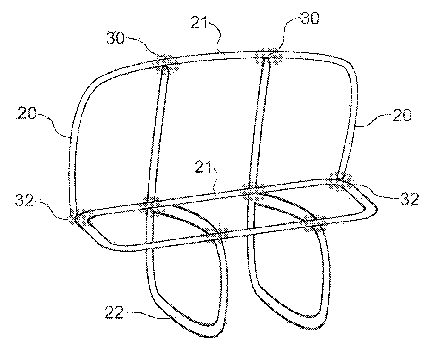
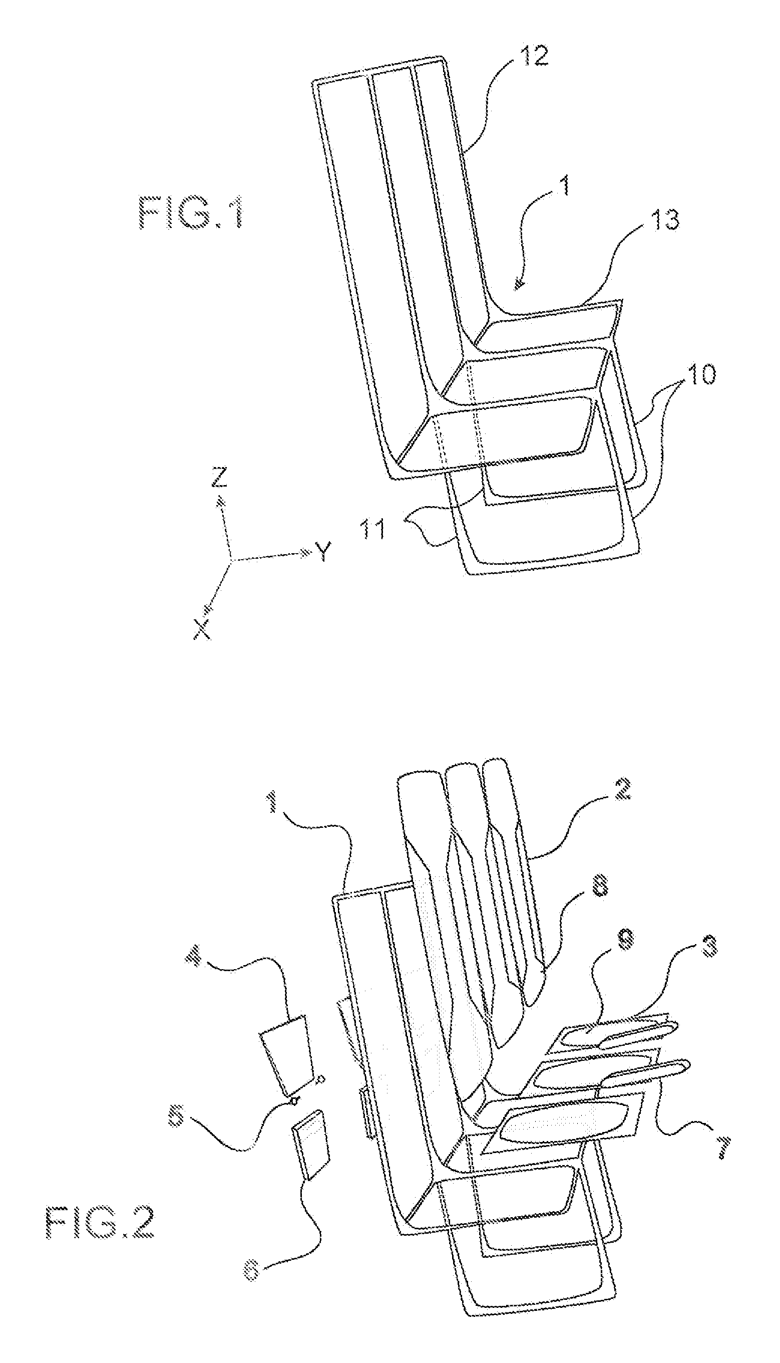
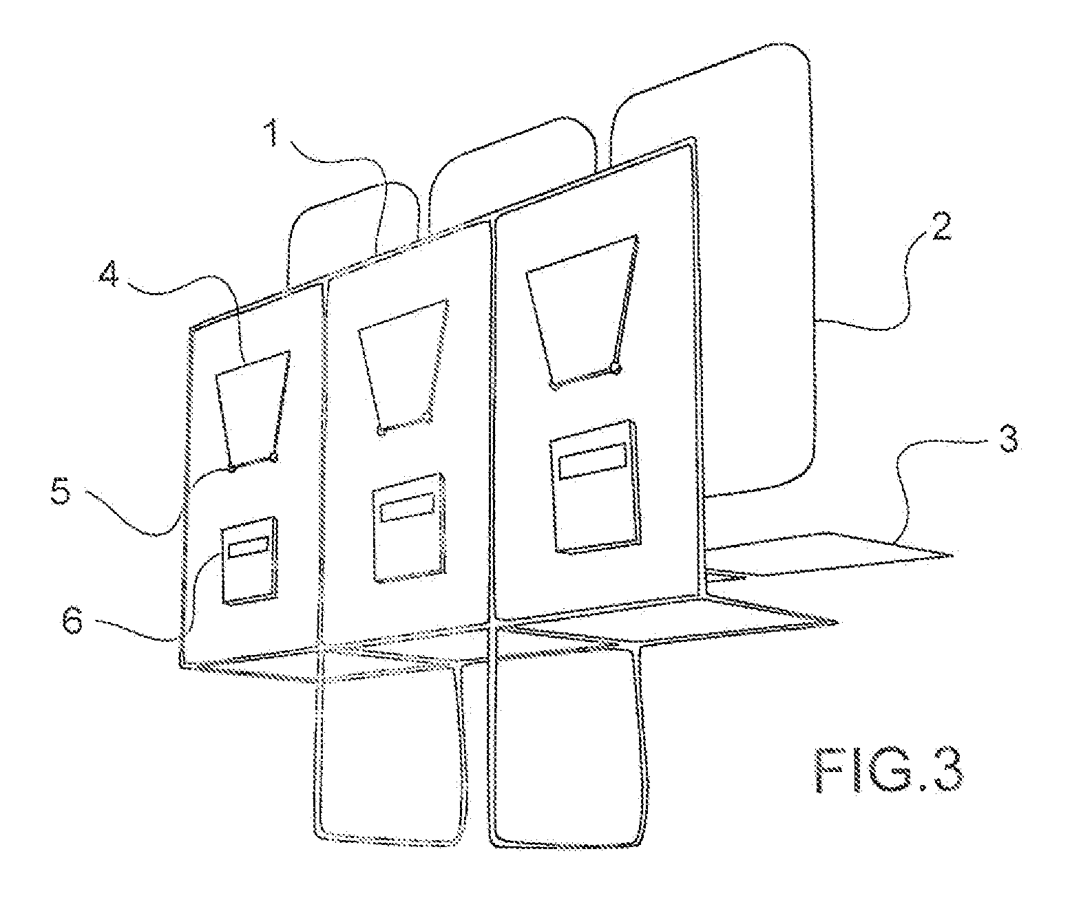
[0017]To this end, a first principal object of the invention is a seat for aircraft passengers including:[0018]a structure including feet attached to the floor of the aircraft, and an armature;[0019]at least one back, and[0020]at lease one base,

[0021]where the at least one back and the at least one base are both securely attached to the armature of the structure.

[0022]According to the invention, the structure is rigid, of tubular design, and made of plastic.

[0023]A preferential embodiment of the invention provides that the plastic of the structure is a polyetherimide resin.

[0024]In a preferential embodiment of the seat according to the invention, the structure is reinforced with fibres consisting of a material of the group including carbon, glass and plant fibres.

[0025]In a first design of ...


PUM


Abstract

The seat for an aircraft passenger is, in particular, very light.It consists principally of a structure (1), a back (2) and a base (3). The structure (1) is rigid and tubular. It may be obtained as a single piece by rotational moulding of a plastic or, alternatively, by extrusion-bending or bladder inflation moulding if the structure (1) consists of several tubes assembled with one another in rigid fashion.Application to civil aircraft seats, in particular in economy class.

Description

TECHNICAL FIELD[0001]The present invention belongs to the field of manufacture of aircraft cabin fittings, for general aviation, commercial aviation or military aeroplanes. It relates more particularly to the production of a seat for an aircraft, supporting one or more passengers.STATE OF THE PRIOR ART[0002]Aircraft seats must satisfy particular standards, notably in terms of impact resistance. A dynamic crash resistance test, for example, subjects the seat to accelerations of 16 g in the aircraft's lengthways axis (axis Y in FIG. 1), 3 g in the perpendicular axis in the aircraft's horizontal plane (axis X in FIG. 1) and 14 g in the aircraft's vertical axis (axis Z of FIG. 1), where g is the acceleration due to gravity (g≈9.81 m·s−2).[0003]To address these constraints aircraft seats intended for passengers have been produced using a large number of parts, generally made of metal. These metal structures are relatively robust, and therefore give the seats great resistance in the event...

Claims


Application Information

Patent Timeline
Patent Type & Authority Patents(United States)
IPC IPC(8): B64D11/06B60N2/68
CPCB64D11/06B60N2/686B64D11/0649Y02T50/46Y02T50/40B64D11/0647
Inventor SAADA, BENJAMIN JACOBSAMUELIAN, JEAN-CHARLES MARCELTEJEDOR, VINCENT
Owner EXPLISEAT
Why Eureka
Try Eureka