Multipurpose concrete anchor clip

a concrete and anchor clip technology, applied in the direction of walls, constructions, building reinforcements, etc., can solve the problems of inability to efficiently and effectively resist uplift, and the typical l-shaped connector may not necessarily handle the variety of loads, so as to achieve minimal waste and optimize material consumption

Active Publication Date: 2015-07-28
SIMPSON STRONG TIE
View PDF265 Cites 28 Cited by
  • Summary
  • Abstract
  • Description
  • Claims
  • Application Information

AI Technical Summary

Benefits of technology

[0015]The present invention provides a connector with two flanges for making a variety of connections between structural members, in particular cold formed steel structural members, with the added utility of a accommodating a heavy bolted connection to one of the structural members with an extended tab on one flange that matches a recess on the other for optimal material consumption and minimal waste in manufacturing.
[0016]The present invention provides a multipurpose connector with a tab extension on one flange that has an outer contour that is exactly equal to the contour of a concave recess on the other flange so that there is no material loss when the connectors are formed from a long coil or strip of material on progressive die stamping machinery.

Problems solved by technology

However, typical L-shaped connectors may not necessarily handle the variety of loads and forces that are sometimes experienced where studs are joined or secured to a floor or other support structure.
More particularly, conventional connector designs may not always efficiently and effectively resist uplift, horizontal and rotational loads that are experienced about connecting points between such studs and an adjacent support structure.

Method used


Image

  • Multipurpose concrete anchor clip
  • Multipurpose concrete anchor clip
  • Multipurpose concrete anchor clip

Examples


Embodiment Construction

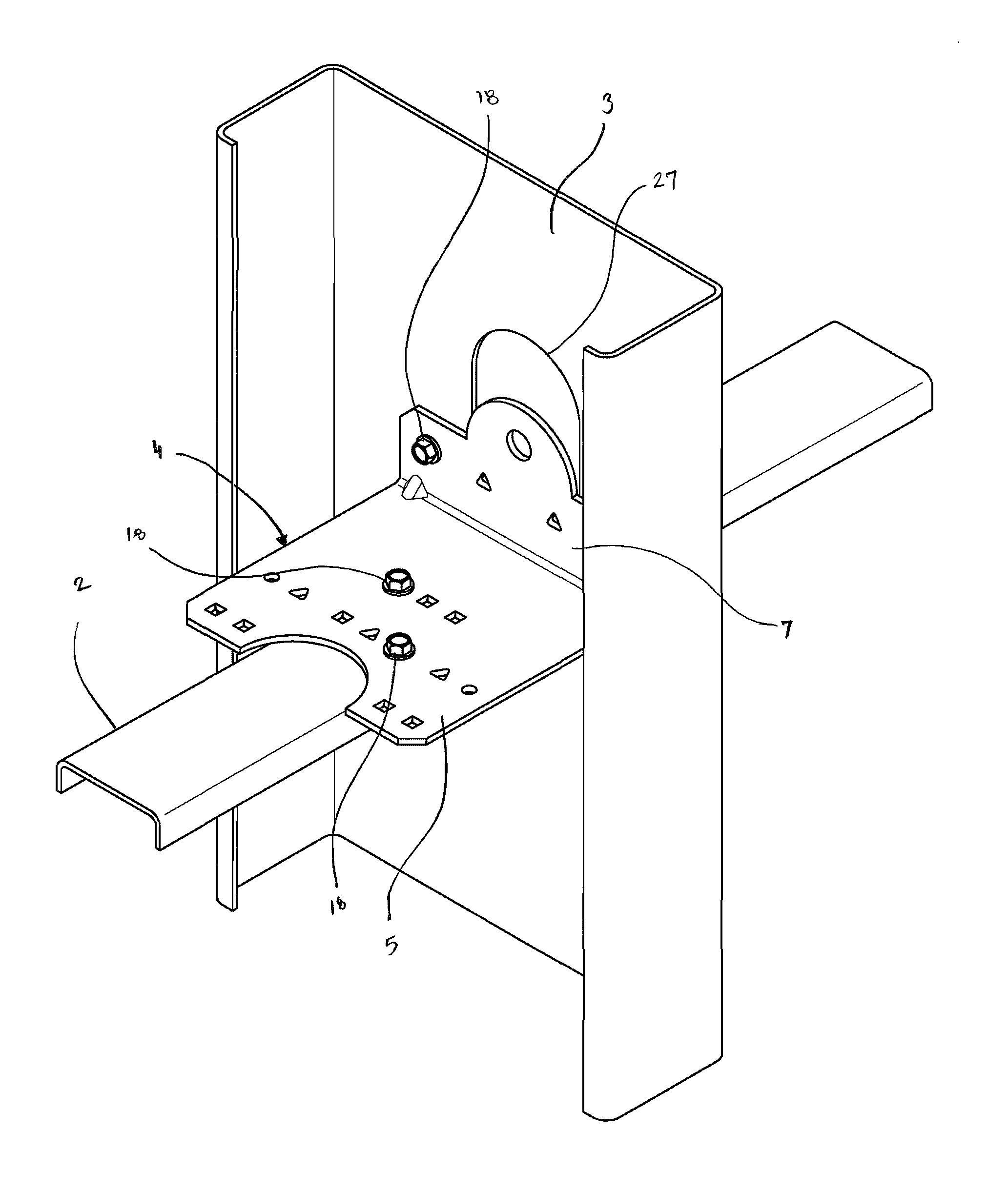
[0020]As best seen in FIGS. 8-10, the present invention is a building connection 1 between a first structural member 2 and a second structural member 3. The first structural member 2 and the second structural member 3 are connected by a multipurpose connector 4 in conjunction with a plurality of fasteners 18.

[0021]Preferably, the building connection comprises the first structural member 2, the second structural member 3, the plurality of fasteners 18, and the multipurpose connector 4.

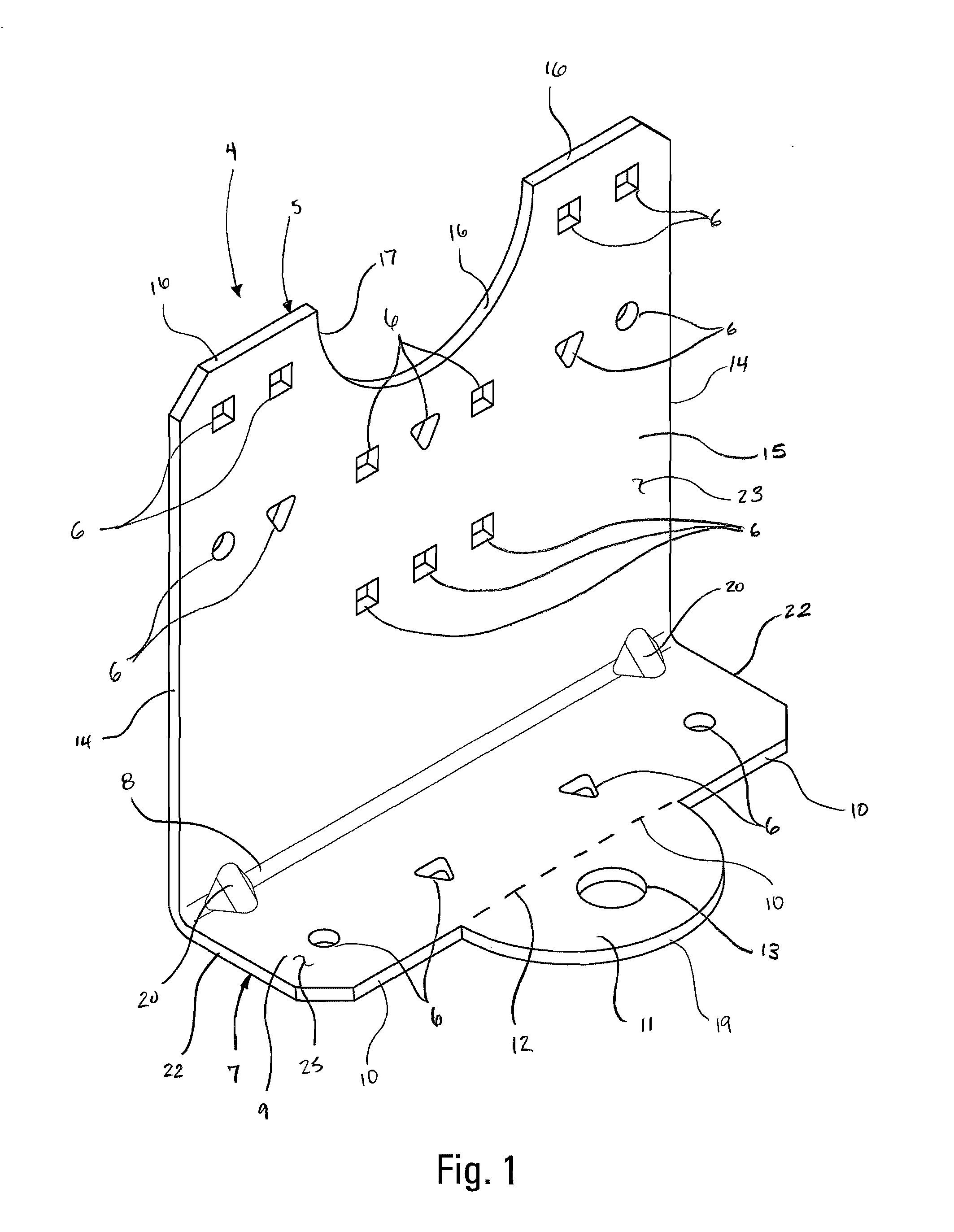
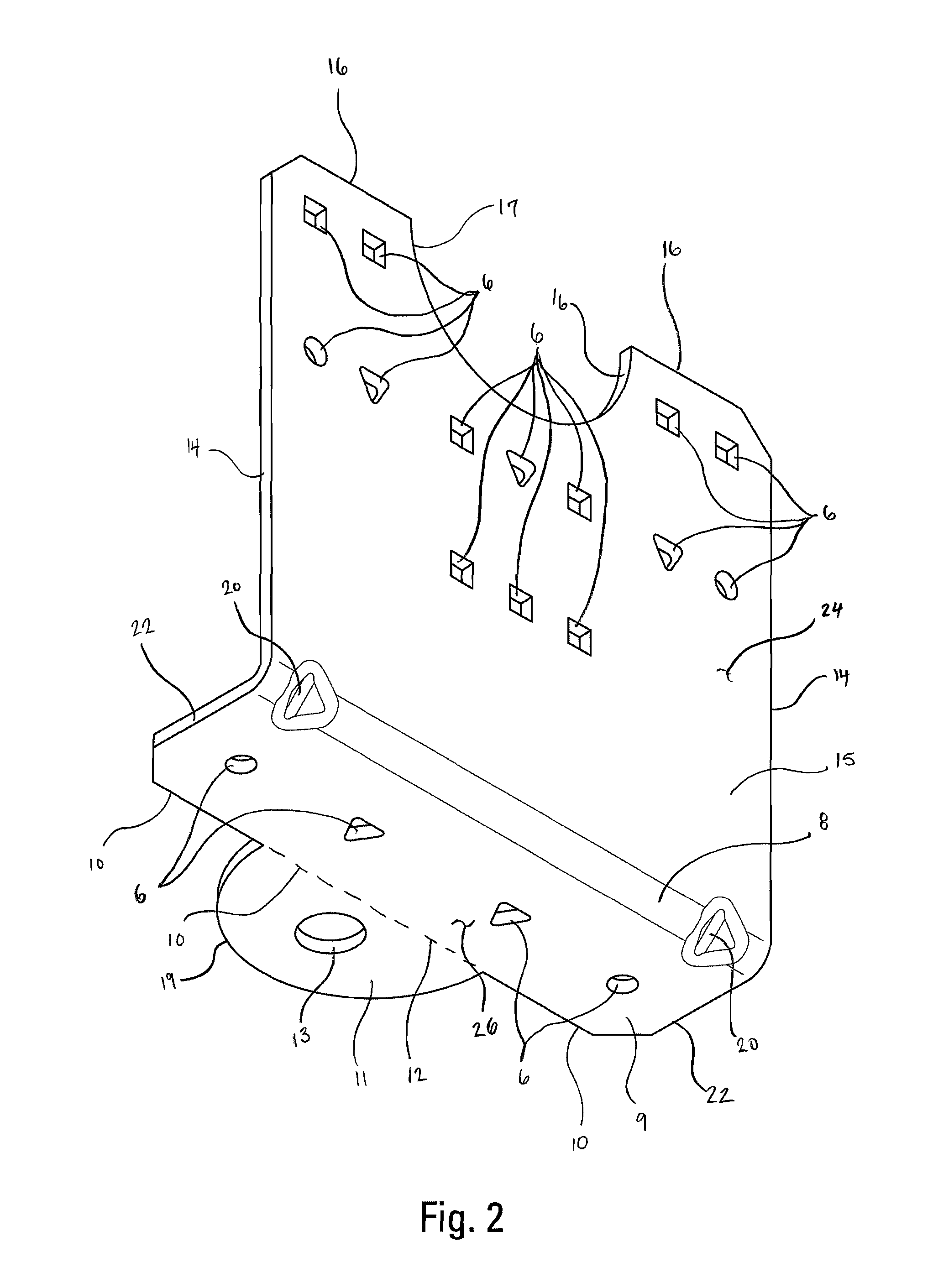
[0022]As best seen in FIGS. 1 and 2, the multipurpose connector 4 preferably comprises a first flange 5 and a second flange 7. Preferably, at least a portion of the first flange 5 is substantially planar, with a first plurality of fastener openings 6. Preferably, at least a portion of the second flange 7 is substantially planar, with a second plurality of fastener openings 6. The second flange 7 preferably is angularly joined to the first flange 5 at a first angular juncture 8 that a first juncture leng...


PUM


Abstract

A connector with two flanges for making a variety of connections between structural members, in particular cold formed steel structural members, with the added utility of a accommodating a heavy bolted connection to one of the structural members with an extended tab on one flange that matches a recess on the other for optimal material consumption and minimal waste in manufacturing.

Description

BACKGROUND OF THE INVENTION[0001]The present invention relates to cold formed steel framing systems, and particularly to anchoring steel studs with anchor bolts embedded in masonry, including poured concrete as well as masonry units.[0002]Many industrial, and a growing number of residential, buildings are constructed with steel stud wall framing for a variety of reasons. Steel framing is fireproof, does not warp, cannot be infested, and does not rot. The majority of connections between structural members are made a right angles, including the connections between vertical framing members, such as wall studs, and the underlying floors and foundations.[0003]Light steel framing is ideal for floors, roofs, support structures for finishes, non-load bearing walls, and even load-bearing walls up to approximately nine stories. With wall systems, whether they are load-bearing or non load-bearing, it is customary to use connectors or clips to secure individual metal studs to overlying and / or u...

Claims


Application Information

Patent Timeline
Patent Type & Authority Patents(United States)
IPC IPC(8): E04B1/38E04C5/06E04B1/41
CPCE04B1/40E04C5/0645E04B2001/405E04B2/763E04B2001/2415E04B2001/2463E04B1/2403E04B2001/389E04B1/24E04B1/388
Inventor STAUFFER, TIMOTHY M.DAUDET, LARRY RANDALLLIN, JIN-JIE
Owner SIMPSON STRONG TIE
Why Eureka
Try Eureka