
Dynamic positioning architecture

a positioning architecture and dynamic technology, applied in the direction of steering initiation, navigation instruments, instruments, etc., can solve the problems of increasing the cost of transceiver battery replacement, affecting the safety of personnel or equipment, and the degree of drift on position measurements will always be present, so as to optimise the overall dp system

Active Publication Date: 2015-08-04
IXSEA +1
View PDF30 Cites 2 Cited by
  • Summary
  • Abstract
  • Description
  • Claims
  • Application Information

AI Technical Summary

Benefits of technology

Significantly improves position keeping, reduces thruster usage and noise, and lowers fuel consumption by up to five times, while maintaining system integrity and accuracy during faults and outages.

Problems solved by technology

In many applications a loss of position beyond the acceptable limits may have a severe impact either on the safety of personnel or equipment, or on the environment.
However, due to physical processes associated with the acceleration due to gravity, plus inherent accuracy and noise within the devices themselves, a degree of drift on position measurements will always be present.
Deep water also increases the cost of replacing batteries in transceivers, which starts to become a significant proportion of the overall cost of the hydro-acoustic positioning system.
Ping stacking only serves to reduce the battery life.
Unfortunately, the increased ping times can adversely affect the DP control.
It tends to lead to higher thrust usage as the DP system detects deviations later and has to apply greater adjustments in thrust.
Any changes in environmental forces or small inconsistencies in the vessel model of the DP system are exacerbated by a long ping time.
There is also the possibility that aliasing effects due to long position measurement periods will introduce increased noise into the position measurements.
During a close approach to a platform or other vessel, however, even small jumps can be ‘uncomfortable’.
Due to its dependence on position measurements continually to estimate the errors in the accelerometers, it is not possible to treat an INS alone as an independent PME unit.

Method used


Image

  • Dynamic positioning architecture
  • Dynamic positioning architecture
  • Dynamic positioning architecture

Examples


Embodiment Construction

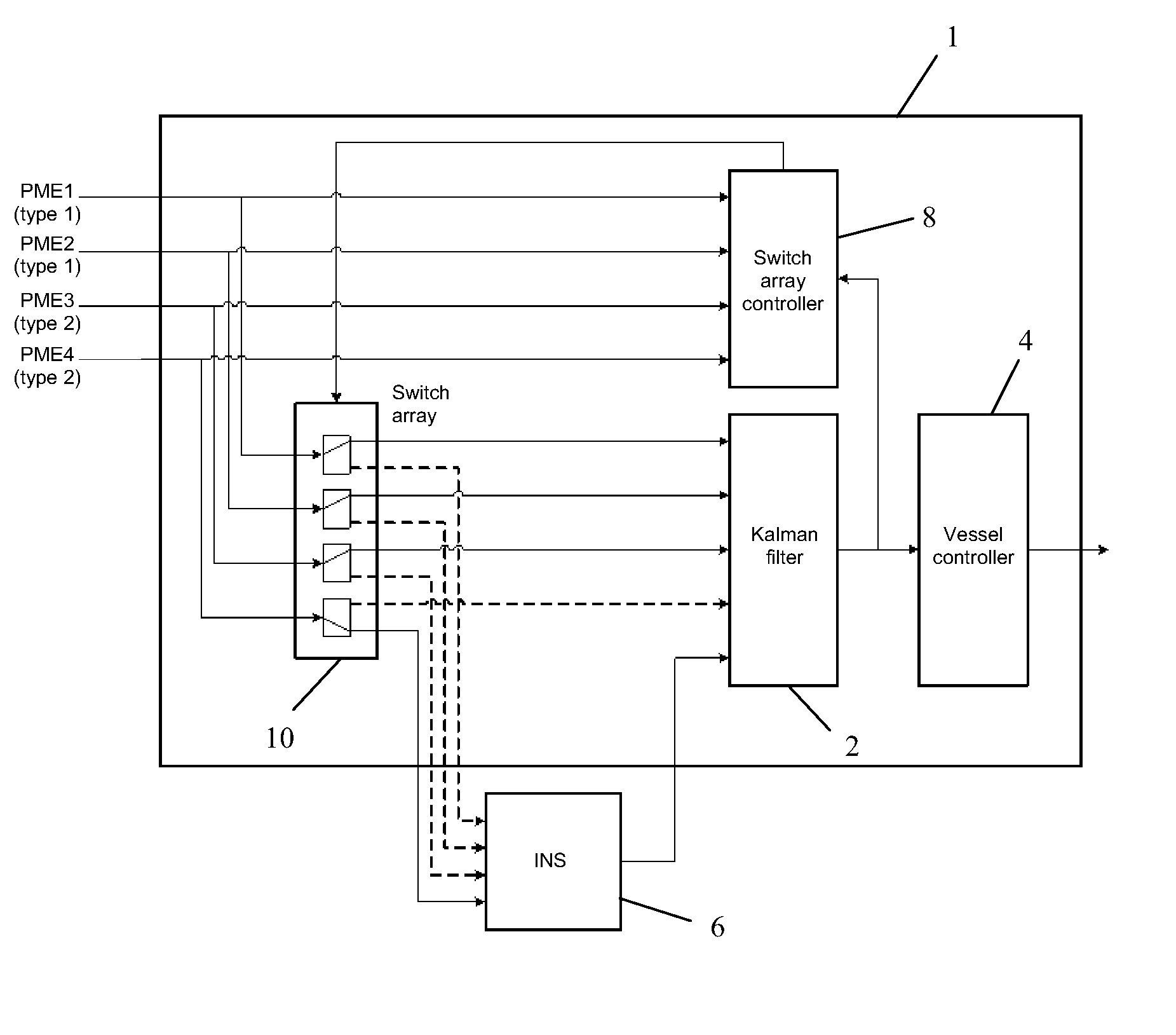
[0071]An improved architecture for a DP system 1 will now be explained with reference to FIGS. 12 and 13.

[0072]A DP system 1 includes a Kalman filter 2 to combine data to estimate a vessel's position and heading and dynamically control them. The output of the Kalman filter 2 is supplied to a vessel control unit 4 that outputs a signal to the thrusters (not shown) to cause them to bring the position of the vessel closer to a desired reference position.

[0073]The data is supplied by a plurality of position measurement equipment (PME) units (not shown) located on the vessel. Two PME units are of the same type (e.g. satellite navigation systems using GPS or DGPS) and the data they supply are labelled PME1 (type 1) and PME2 (type 1). Another two PME units are also of the same type (e.g. hydro-acoustic positioning systems) and the data that they supply are labelled PME3 (type 2) and PME4 (type 2).

[0074]An inertial navigation system (INS) unit 6 is integrated with the DP system. The INS uni...


PUM


Abstract

The present invention provides an improved architecture for integrating an inertial navigation system (INS) into a dynamic positioning (DP) system for a vessel. The architecture includes an INS unit and a DP system having a Kalman filter or other algorithm for combining data supplied by a plurality of position measuring equipment (PME) and the INS unit to derive an estimate of the position or speed of the vessel. A switch array and a switch array controller are also provided. These may optionally form a part of the DP system. The switch array is operable under the control of the switch array controller to supply data supplied by one or more of the plurality of position measuring equipment to the INS unit for the purposes of correcting drift. The selection of which of the one or more PME is / are to be combined with the INS unit is made automatically, in real time, to dynamically optimise the DP system.

Description

CROSS REFERENCE TO RELATED APPLICATION[0001]This application claims priority to European Patent Application No. 0801567.3 filed Sep. 5, 2008.FIELD OF THE INVENTION[0002]The invention relates to an architecture for the dynamic positioning (DP) of marine vessels, i.e. the use of thrusters to maintain the position of a vessel in the vicinity of a reference point and stabilise its heading, in opposition to environmental forces such as wind and current. The architecture is particularly concerned with the way in which an inertial navigation system (INS) can be integrated with the DP system.[0003]The term “vessels” is intended to include ships, drilling rigs and any other surface-going vessels or platforms or submersible (submarine) vessels. The invention is principally relevant to applications in deep water but the use herein of the word “marine” is not intended to exclude its application in freshwater lakes or other shallow water.[0004]The term “inertial navigation system (INS)” is inten...

Claims


Application Information

Patent Timeline
Patent Type & Authority Patents(United States)
IPC IPC(8): G01C21/00G05D1/02G01C21/16B63H25/04B63H25/42
CPCB63H25/04B63H25/42G01C21/16G05D1/0206G05D1/0208G01C21/183
Inventor STEPHENS, RICHARD IANCHAMBERLAIN, ANDREW GRAHAMCRETOLLIER, FRANCOIS
Owner IXSEA
Learn More