Optical observation device with at least one visual observation beam path
a technology of optical observation and beam path, which is applied in the field of optical observation devices with at least one visual observation beam path, can solve the problems of often requiring a larger space than the actual basic prism system, and achieve the effect of less physical space for the inward reflection module and high transmission of the observation beam path
- Summary
- Abstract
- Description
- Claims
- Application Information
AI Technical Summary
Benefits of technology
Problems solved by technology
Method used
Image
Examples
first embodiment
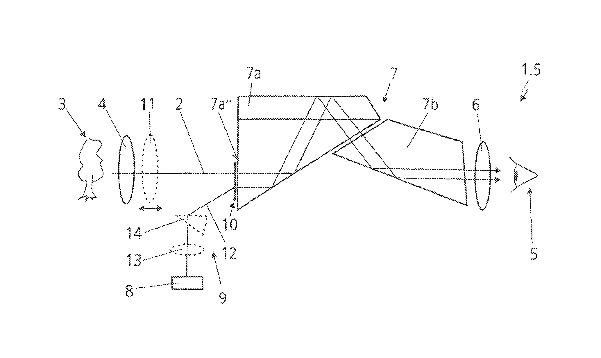
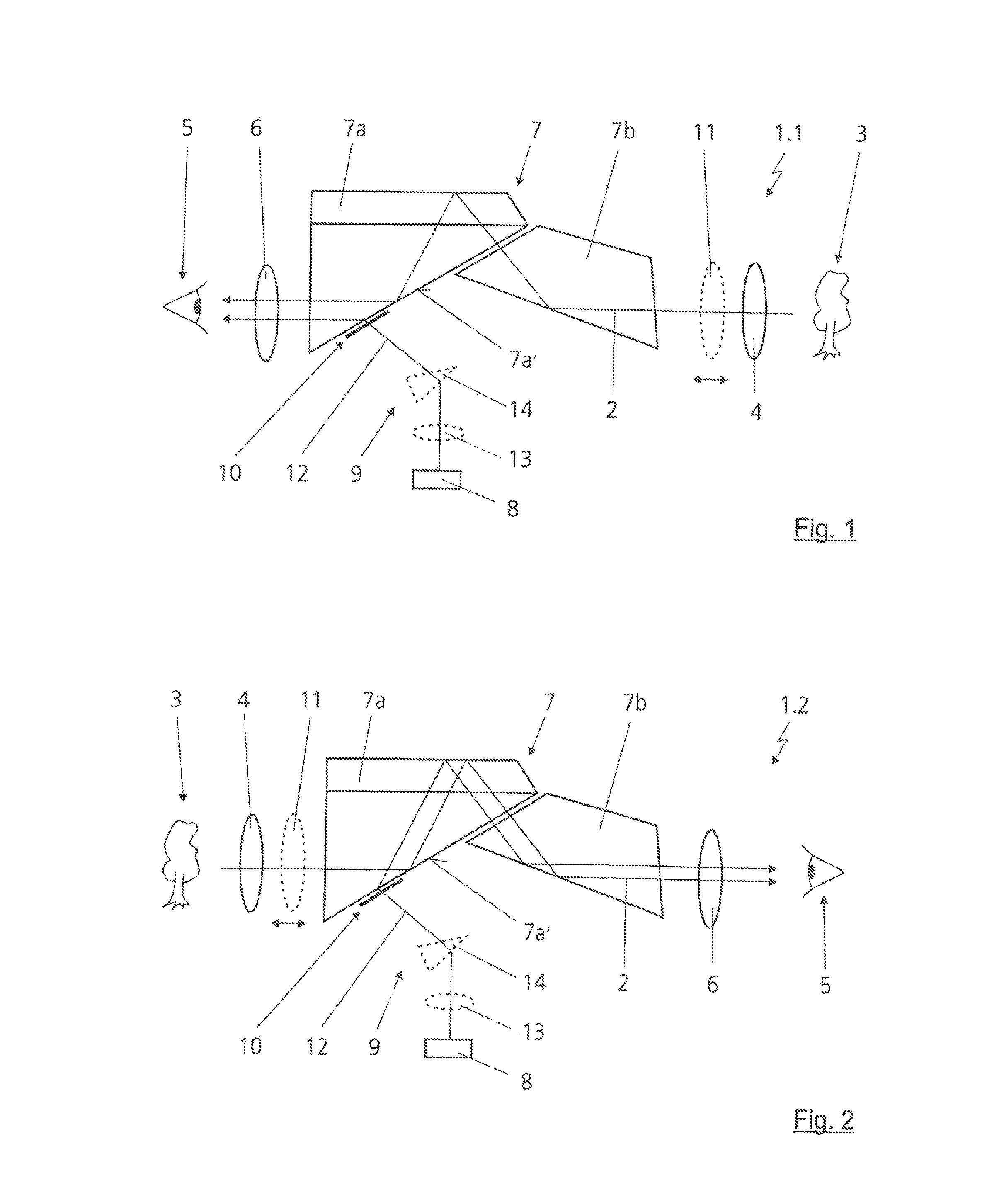
[0039]FIG. 1 illustrates an inventive optical observation device 1.1 in a first embodiment with a visual observation beam path 2 which has an objective lens 4, that is to be turned in an operating position to a target object 3 to be observed and images the target object 3, and an eyepiece 6 that is to be turned to an eye 5 of an observer. An Abbe König prism system 7 for imaging version image inversion of the visual observation beam path 2 is arranged in the visual observation beam path 2 between the objective lens 4 and the eyepiece 6. The Abbe König prism system7 has a roof prism 7a and an isosceles prism 7b. As regards further details of the Abbe König prism system 7, reference is made to DE 10 2008 003 414 A1 quoted at the beginning, which likewise discloses binoculars with an Abbe König prism system. For reasons of space, in particular, the roof prism 7a is frequently arranged in the direction of the eyepiece 6 in the visual observation beam path 2. In addition, the roof prism ...
second embodiment
[0048]an inventive optical observation device 1.2 is illustrated in FIG. 2. Here, the Abbe König prism system 7 is arranged inverted in the optical observation device 1.2, that is to say that the roof prism 7a is not turned to the eye 5 of the observer, but to the objective lens 4 or the target object 3.
[0049]The holographic layer 10 can be applied directly to the face 7a′ of the roof prism 7a by direct exposure of a photosensitive layer such as, for example, silver salt. Furthermore, it is possible to introduce the holographic layer 10 into the face 7a′ of the roof prism 7a as a laser engraving. The holographic layer 10 can also be produced as a plastic pressed hologram or in another, generally known technique for holographic fabrication.
third embodiment
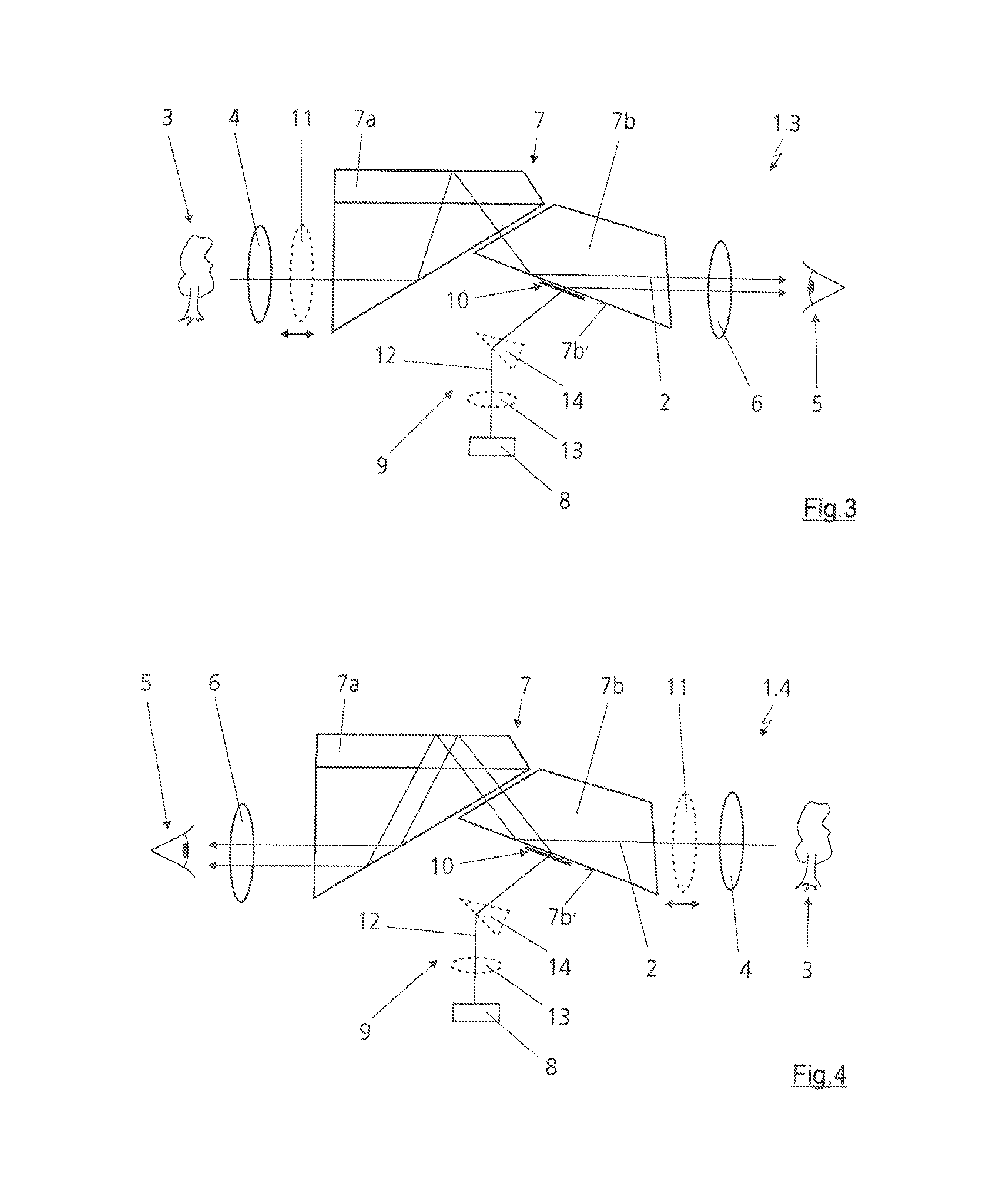
[0050]FIG. 3 illustrates an inventive optical observation device 1.3. The holographic layer 10 is applied in this case to a face 7b′ of the isosceles prism 7b of the Abbe König prism system 7.
[0051]FIG. 4 shows a fourth embodiment of an inventive optical observation device 1.4. By contrast with the third embodiment of the inventive optical observation device 1.3 from FIG. 3, in this case it is only the Abbe König prism system 7 that is arranged in an inverted fashion, and so the roof prism 7a is turned to the eye 5 of the observer.
PUM
 Abstract
Description
Claims
Application Information
 - R&D
- Intellectual Property
- Life Sciences
- Materials
- Tech Scout
- Unparalleled Data Quality
- Higher Quality Content
- 60% Fewer Hallucinations
Browse by: Latest US Patents, China's latest patents, Technical Efficacy Thesaurus, Application Domain, Technology Topic, Popular Technical Reports.
© 2025 PatSnap. All rights reserved.Legal|Privacy policy|Modern Slavery Act Transparency Statement|Sitemap|About US| Contact US: help@patsnap.com


