
Position sensing systems for use in touch screens and prismatic film used therein

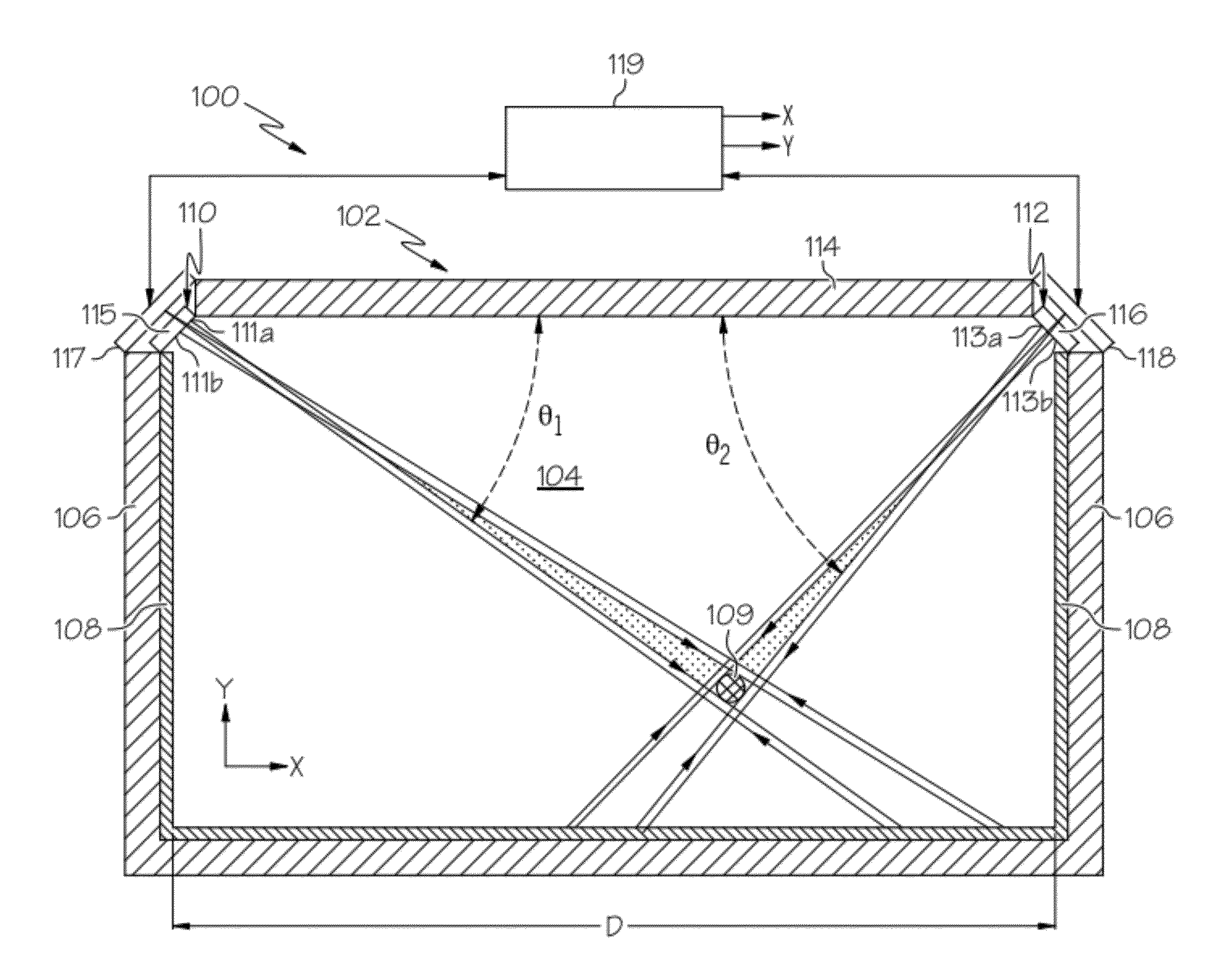
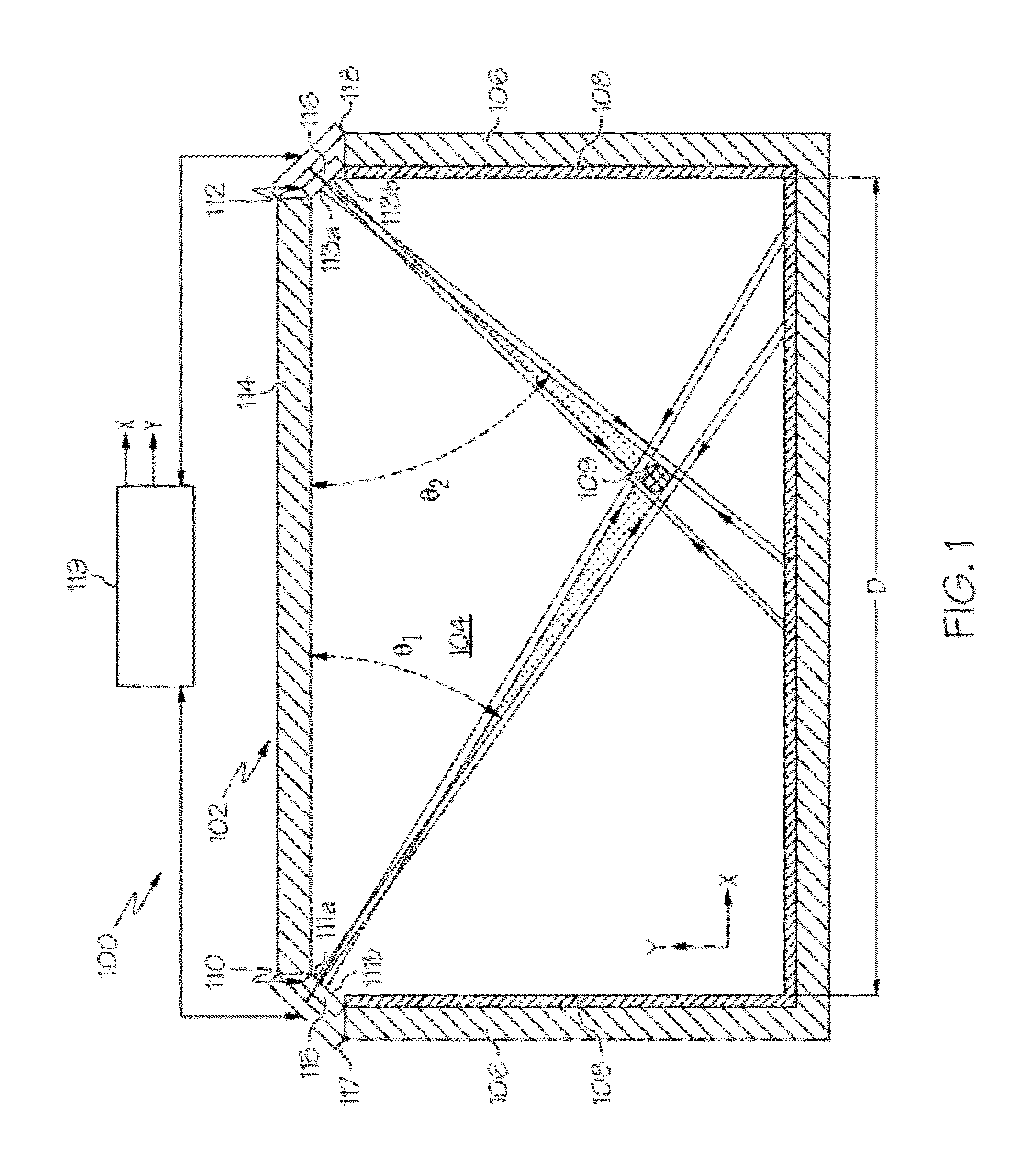
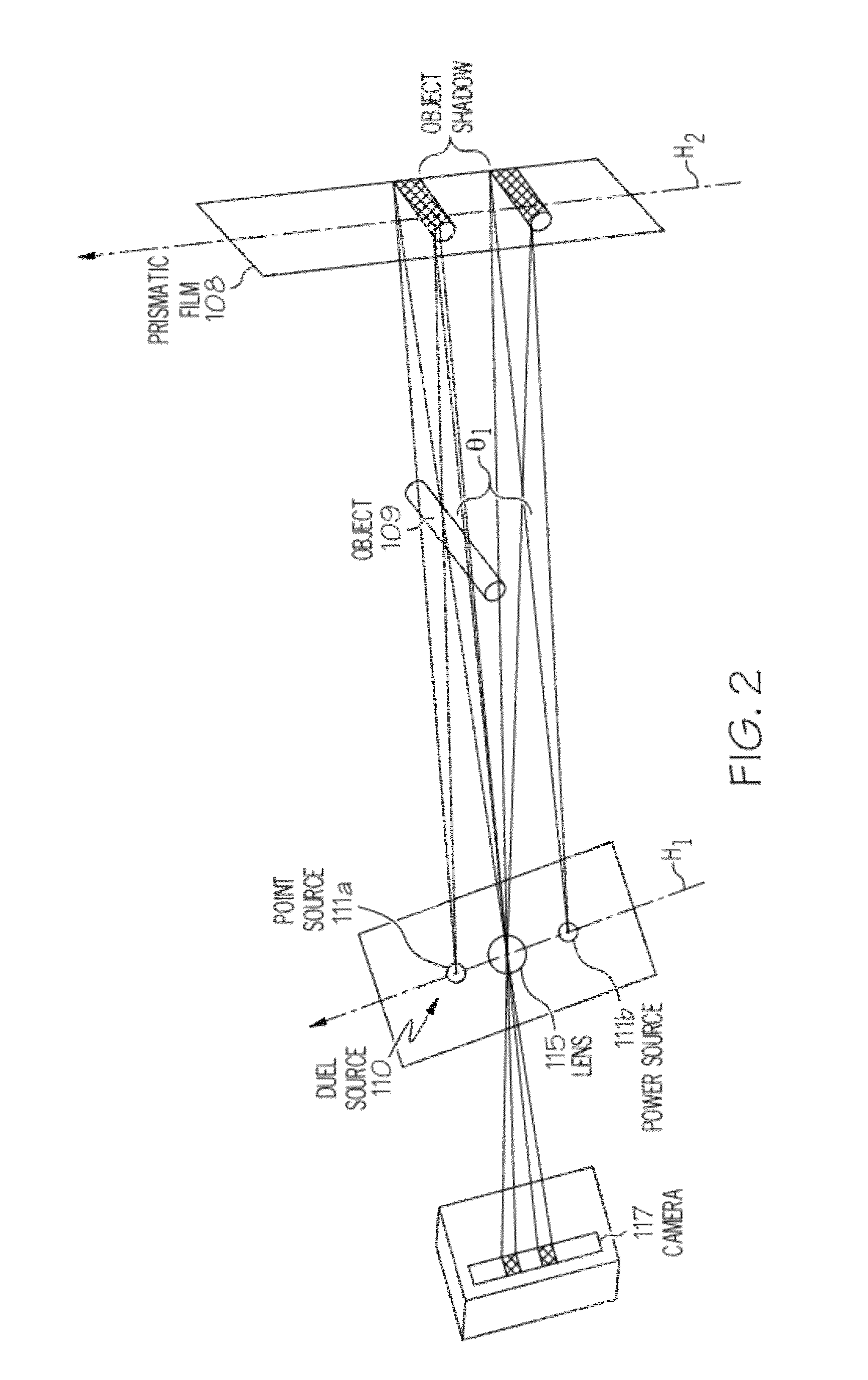
a technology of position sensing and touch screen, which is applied in the direction of static indicating devices, lighting and heating apparatus, instruments, etc., can solve the problems of inability to determine with certainty the coordinate location of the two interposing objects, and the configuration of the touch screen can only reliably detect a single touch, so as to maximize the parallax effect and maximize the perpendicularity of the camera

Active Publication Date: 2015-08-04
AVERY DENNISON CORP +1
View PDF51 Cites 8 Cited by
  • Summary
  • Abstract
  • Description
  • Claims
  • Application Information

AI Technical Summary

Benefits of technology

The patent text describes a technology related to touch-screen cameras. The first aspect of the invention is the collocation of both the source and detector in the touch-screen plane, which minimizes the size of the camera perpendicular to the screen and maximizes parallax effects. The third aspect is the provision of a prismatic film that is brightly retroreflective over a wide range of observation angles. This is achieved by using a plurality of triangular cube corner retroreflective elements with specific dihedral angle errors and a metallized layer for further enhancement of retroreflectivity. Overall, this technology enhances the performance of touch-screen cameras and improves the user experience.

Problems solved by technology

While such prior touch-screen configurations are generally adequate for their intended purpose, the applicant has observed that such touch-screen configurations can only reliably detect a single touch at one time.
Since it may not be clear which dip in the second camera signal corresponds to a given dip in the first camera signal, the resulting signal data may be ambiguous, making it impossible to determine with certainty the coordinate location of the two interposing objects.

Method used


Image

  • Position sensing systems for use in touch screens and prismatic film used therein
  • Position sensing systems for use in touch screens and prismatic film used therein
  • Position sensing systems for use in touch screens and prismatic film used therein

Examples


Embodiment Construction

[0032]The present invention is now illustrated in greater detail by way of the following detailed description which represents the best presently known mode of carrying out the invention. However, it should be understood that this description is not to be used to limit the present invention, but rather, is provided for the purpose of illustrating the general features of the invention.

[0033]One disadvantage of using arrays of prisms with positive cant in a touch-screen is the phenomenon of “sparkles.” At certain entrance angles, light from the LED can enter the prismatic film, bounce off of just two of the cube corner faces and return to the camera aperture. This creates a sharp “spike” in the camera signal at that particular angle.

[0034]The presence of “spikes” in the camera signal is undesirable. So for many applications, it is desirable to choose a cant for which sparkles only occur at entrance angles not seen in the touch-screen geometry. Typical touch-screens see entrance angles...


PUM


Abstract

A dual light-source position detecting system for use in touch screens is provided that utilizes parallax to determine the position of an interposing object, and a prismatic film that is brightly retroreflective over a broad entrance angle to enhance to accuracy of the parallax determination of position. The position detecting system includes at least one camera positioned to receive light radiation traversing a detection area and that generates a signal representative of an image; two spaced-apart sources of light radiation, which may be LEDs, or IR emitters positioned adjacent to the camera for outputting light radiation that overlaps over at least a portion of a detection area, and a prismatic film positioned along a periphery of at least a portion of the detection area that retroreflects the light radiation from the two sources to the camera.

Description

CROSS-REFERENCE TO RELATED APPLICATIONS[0001]The present application claims the benefit of U.S. Provisional Application Nos. 61 / 285,684 filed Dec. 11, 2009, and 61 / 406,644 filed Oct. 26, 2010, both of which are incorporated herein by reference in their entireties.FIELD OF THE INVENTION[0002]The present invention relates generally to a system and method for detecting the position of an object within a touch screen or a position sensing system and a retroreflective or prismatic film used thereby. More specifically, the invention concerns a low profile position detecting system for use in touch screens or position sensing systems that employs a large spacing between source and detector in the plane of the screen, and a prismatic film that is brightly retroreflective at larger observation angles, and over a broad range of entrance angles.BACKGROUND OF THE INVENTION[0003]Some position detection systems related to touch screens sense the interruption of radiation (e.g., light) by an inter...

Claims


Application Information

Patent Timeline
Patent Type & Authority Patents(United States)
IPC IPC(8): G06F3/042
CPCG06F3/0428G06F3/0304G06F3/0416G06F3/0425
Inventor CHAPMAN, STEVENBRIDGER, SIMON
Owner AVERY DENNISON CORP
Learn More