Crimp terminal
a crimp terminal and open-barrel technology, applied in the direction of electrical equipment, connections, effected by permanent deformation, etc., can solve the problems of deterioration of crimping performance, and achieve the effect of reducing the deformation of the terminal, increasing the stress that acts on the conductor (an element wire) of the electrical wire, and increasing the cross-sectional secondary momen
- Summary
- Abstract
- Description
- Claims
- Application Information
AI Technical Summary
Benefits of technology
Problems solved by technology
Method used
Image
Examples
first embodiment
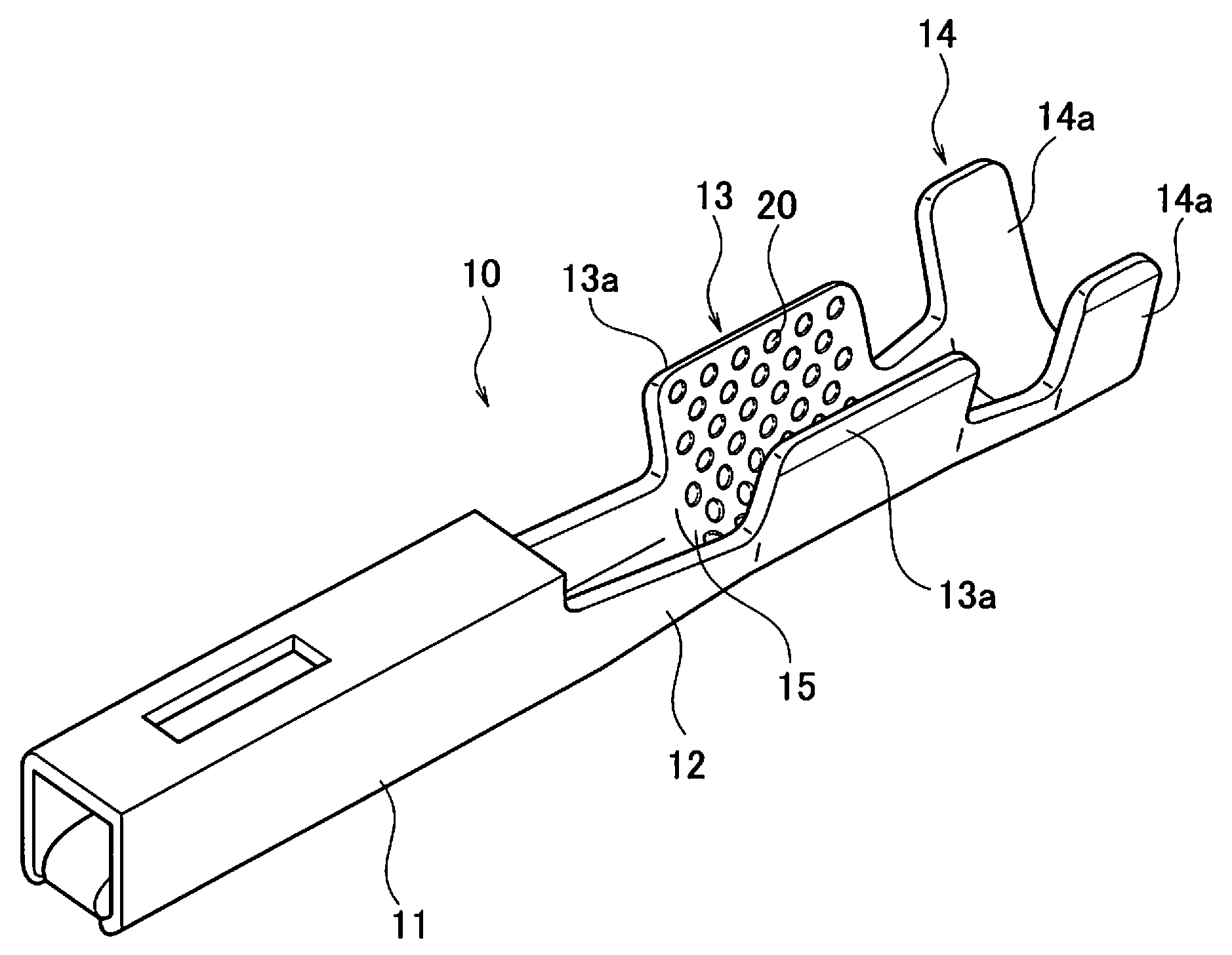
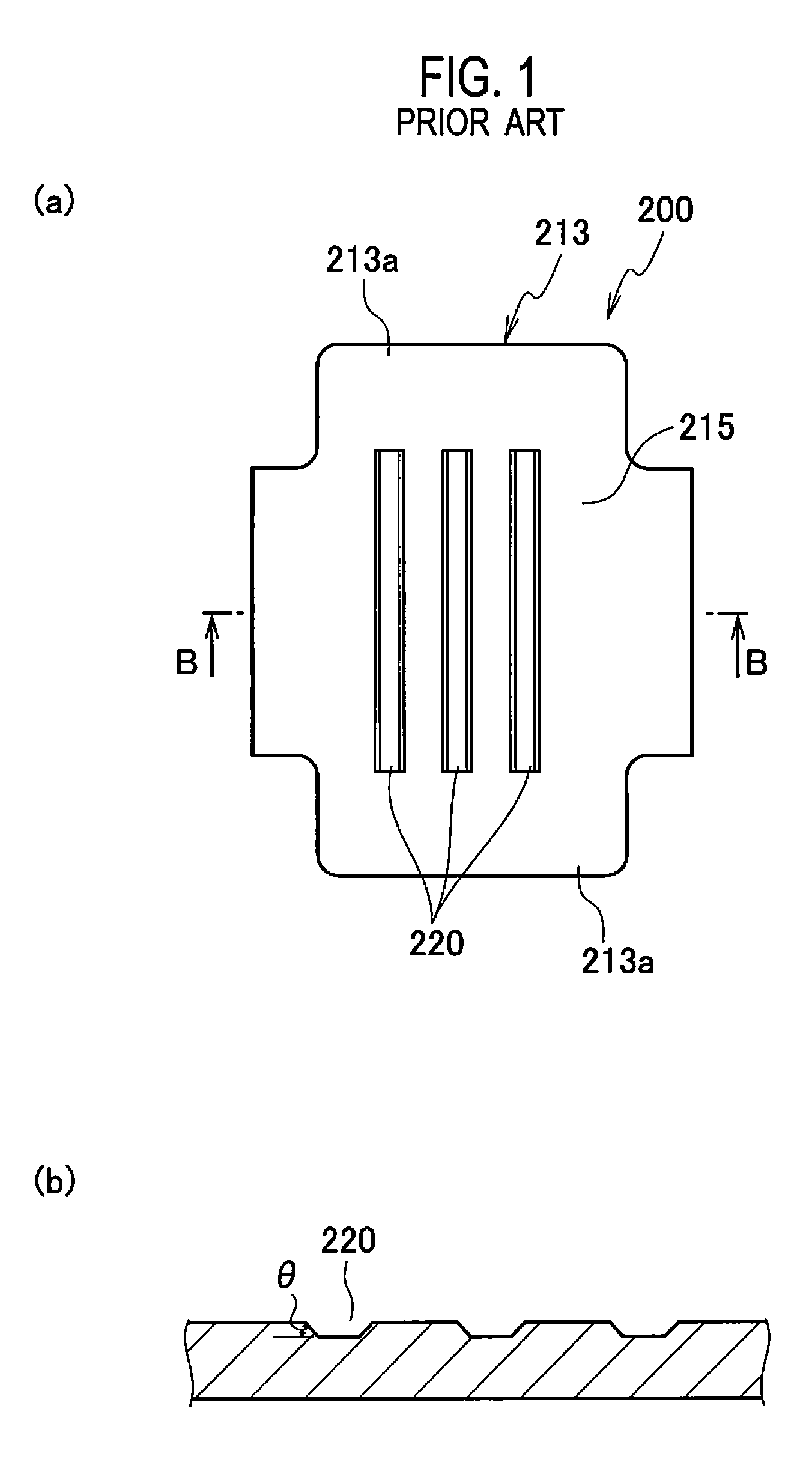
[0037]FIG. 3 is an external perspective view of a crimp terminal. FIG. 4 is a plan view showing an expanded shape of a conductor crimping portion of the crimp terminal. FIG. 5 is an enlarged cross-sectional view of small circular concave portions in a state before crimping of the conductor crimping portion. FIGS. 6(a) to 6(d) are enlarged cross-sectional views schematically and sequentially showing a condition in which a conductor gets into the small circular concave portion of the conductor crimping portion while causing a plastic deformation at the time of crimping.
[0038]As shown in FIG. 1, a crimp terminal 10 is a female terminal and includes an electrical connection portion 11, a link portion 12, a conductor crimping portion 13 and a sheath crimping portion 14. The box-type electrical connection portion 11 is provided at a front in a longitudinal direction of the terminal (in a longitudinal direction of a conductor of an electrical wire connected to the terminal, i.e., in a dire...
second embodiment
[0066]FIG. 8 is a cross-sectional view of the small circular concave portions 20 as the serration in a crimp terminal according to a second embodiment of the present invention.
[0067]In the crimp terminal of the present embodiment, the serration angle θ between the extension surface 21a of the inner bottom surface 21 and the inner side surface 22 of each small circular concave portion 20 is set to be 70 degrees.
[0068]The diameter “d” of the inner bottom surface of the small circular concave portion 20 is set to be 0.3 mm. The shortest distance “b” of a flat surface portion between peripheries of mutually adjacent small circular concave portions 20 is set to be 0.15 mm.
[0069]In this case, r1 and r2 of the model used for calculating a cross-sectional secondary moment have values of 0.15 mm and 0.3 mm, respectively. It is to be noted that a radius of a top surface of the concave portion 20 is not employed because a round is applied to the periphery thereof and the radius is difficult to...
third embodiment
[0071]FIG. 11 is explanatory views of a crimp terminal according to a third embodiment of the present invention. Specifically, FIG. 11(a) is a plan view showing an expanded shape of a conductor crimping portion, and FIG. 11(b) is an arrow cross-sectional view taken along a line A-A of FIG. 11(a).
[0072]In the present embodiment, in order to reduce a size of the terminal, the number of small circular concave portions 20 provided as the serrations is less than that in the first embodiment.
[0073]In addition, linear convex portions 25 for restricting extension in a front-rear direction of the conductor of the electrical wire at the time of crimping are provided at a front and a rear of a region where the small circular concave portions 20 as the serrations are scattered, so as to intersect in a terminal width direction. The other configurations are similar to that of the first embodiment. Accordingly, the small circular concave portions 20 are provided similarly to the first embodiment, ...
PUM
 Abstract
Description
Claims
Application Information
 - R&D
- Intellectual Property
- Life Sciences
- Materials
- Tech Scout
- Unparalleled Data Quality
- Higher Quality Content
- 60% Fewer Hallucinations
Browse by: Latest US Patents, China's latest patents, Technical Efficacy Thesaurus, Application Domain, Technology Topic, Popular Technical Reports.
© 2025 PatSnap. All rights reserved.Legal|Privacy policy|Modern Slavery Act Transparency Statement|Sitemap|About US| Contact US: help@patsnap.com


