Check patentability & draft patents in minutes with Patsnap Eureka AI!

Method and magnetic resonance system for determining a coding for a flow measurement and for implementing a flow measurement with the coding

a magnetic resonance system and flow measurement technology, applied in the field of magnetic resonance system for determining flow measurement coding and implementing flow measurement with coding, can solve the problems of inability to quantitatively evaluate the measurement data of phase contrast flow measurement, and inability to accurately measure the flow. the effect of coding

Inactive Publication Date: 2015-08-11
SIEMENS HEALTHCARE GMBH
View PDF10 Cites 0 Cited by
  • Summary
  • Abstract
  • Description
  • Claims
  • Application Information

AI Technical Summary

Benefits of technology

The invention provides a method for measuring flow (such as pressure) that is easier and faster than previous methods. This method uses a flow coding that automatically adapts to the flow velocity in a specific area, resulting in more accurate and reproducible results.

Problems solved by technology

If the flow coding is too strong, signal aliasing (folding) occurs in the phase contrast image, in particular in a vessel, this signal aliasing making a quantitative evaluation of the measurement data of the phase contrast flow measurement impossible.
Conversely, if the flow coding is too weak, the contrast in the flow representation is too low and the precision in the flow quantification is likewise negatively affected.
However, this is complicated and time-consuming since the flow measurement must thereby be repeated at least once, and additionally the measurement data must be loaded into a post-processing environment during the measurement workflow and be analyzed there.In a prior measurement, phase contrast measurement data with different codings are measured in a protocol.
In addition to the likewise increased measurement effort, this method is imprecise since corresponding compromises in the spatial and temporal resolution are necessary given a use of multiple codings in a flow measurement, such that the determined optimal coding does not necessary exhibit optimal results in the actual flow measurement.

Method used


Image

  • Method and magnetic resonance system for determining a coding for a flow measurement and for implementing a flow measurement with the coding
  • Method and magnetic resonance system for determining a coding for a flow measurement and for implementing a flow measurement with the coding
  • Method and magnetic resonance system for determining a coding for a flow measurement and for implementing a flow measurement with the coding

Examples


Embodiment Construction

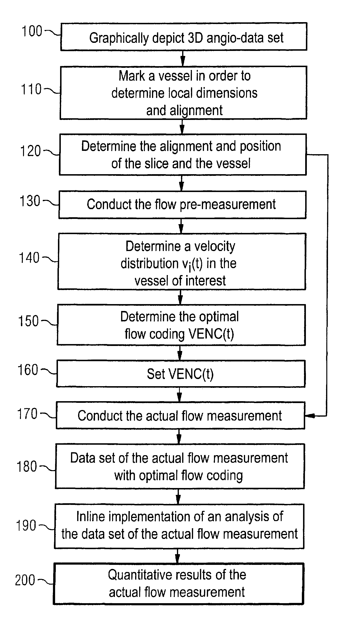
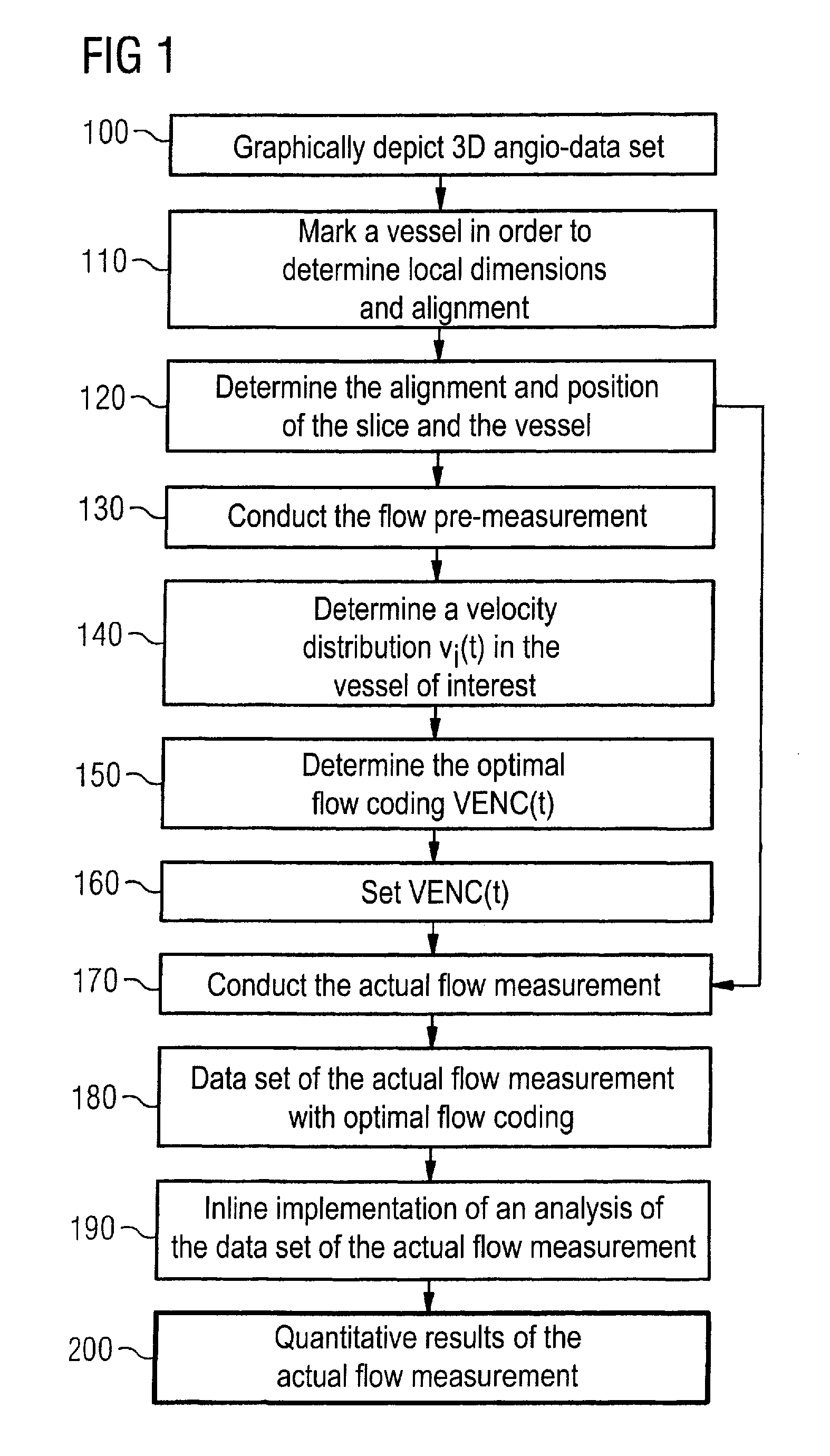
[0042]FIG. 1 shows a flow plan of a flow measurement with an automatic optimization of the flow coding that is used.

[0043]A three-dimensional angiogram is implemented in Step 100 and the data set that is thereby obtained is graphically depicted.

[0044]A vessel which is graphically shown by means of the data set obtained via the angiogram is marked in Step 110 in order to determine dimensions of the vessel (for example a diameter and a curvature radius) as well as an alignment of the vessel via this marking.

[0045]The position or orientation of a slice is determined in the next Step 120 using the dimensions and the alignment of the vessel such that an optimal measurement of flow speeds within the vessel can ensue by means of this slice.

[0046]In the event that the flow coding for the actual flow measurement which is to be implemented in the predetermined slice is already known (for example since it was already defined beforehand), the workflow branches to Step 170. Otherwise, the method...


PUM


Abstract

In a method and magnetic resonance system to determine a flow coding for a flow measurement with the magnetic resonance system, in order to determine the optimal flow coding, a flow pre-measurement with multiple different flow codings is conducted within a slice within a body to be examined, each of these codings allowing flow velocities to be detected with a sensitivity dependent on the respective coding. A velocity distribution of the non-slice-location-specific flow velocity values is generated from all of the results of this flow pre-measurement by a common Fourier transformation. The optimal flow coding for the flow measurement is then determined based on this velocity distribution.

Description

BACKGROUND OF THE INVENTION[0001]1. Field of the Invention[0002]The present invention concerns a method to determine as optimal a coding as possible for a flow measurement in a magnetic resonance system. The present invention also concerns a method to conduct a flow measurement with the determined optimal coding. The invention also concerns a magnetic resonance system to implement such methods.[0003]2. Description of the Prior Art[0004]In order to operate with as optimal a speed coding as possible in a phase contrast flow measurement conducted with a magnetic resonance system, according to the prior art time-consuming measurements must be used. If the flow coding is too strong, signal aliasing (folding) occurs in the phase contrast image, in particular in a vessel, this signal aliasing making a quantitative evaluation of the measurement data of the phase contrast flow measurement impossible. Conversely, if the flow coding is too weak, the contrast in the flow representation is too l...

Claims


Application Information

Patent Timeline
Patent Type & Authority Patents(United States)
IPC IPC(8): A61B5/05G01R33/563A61B5/00A61B5/02A61B5/055G01R33/54
CPCA61B5/02007A61B5/055A61B5/7257G01R33/56316G01R33/543G01R33/546
Inventor GREISER, ANDREAS
Owner SIEMENS HEALTHCARE GMBH
Features
  • R&D
  • Intellectual Property
  • Life Sciences
  • Materials
  • Tech Scout
  • Unparalleled Data Quality
  • Higher Quality Content
  • 60% Fewer Hallucinations
Learn More