
Front spoiler apparatus for vehicle

a technology for spoilers and vehicles, applied in vehicle components, vehicle body streamlining, road transportation emission reduction, etc., can solve the problems of increasing weight, deteriorating fuel efficiency and cost, and reducing durability, so as to prevent noise production

Active Publication Date: 2015-08-11
HYUNDAI MOTOR CO LTD
View PDF19 Cites 36 Cited by
  • Summary
  • Abstract
  • Description
  • Claims
  • Application Information

AI Technical Summary

Benefits of technology

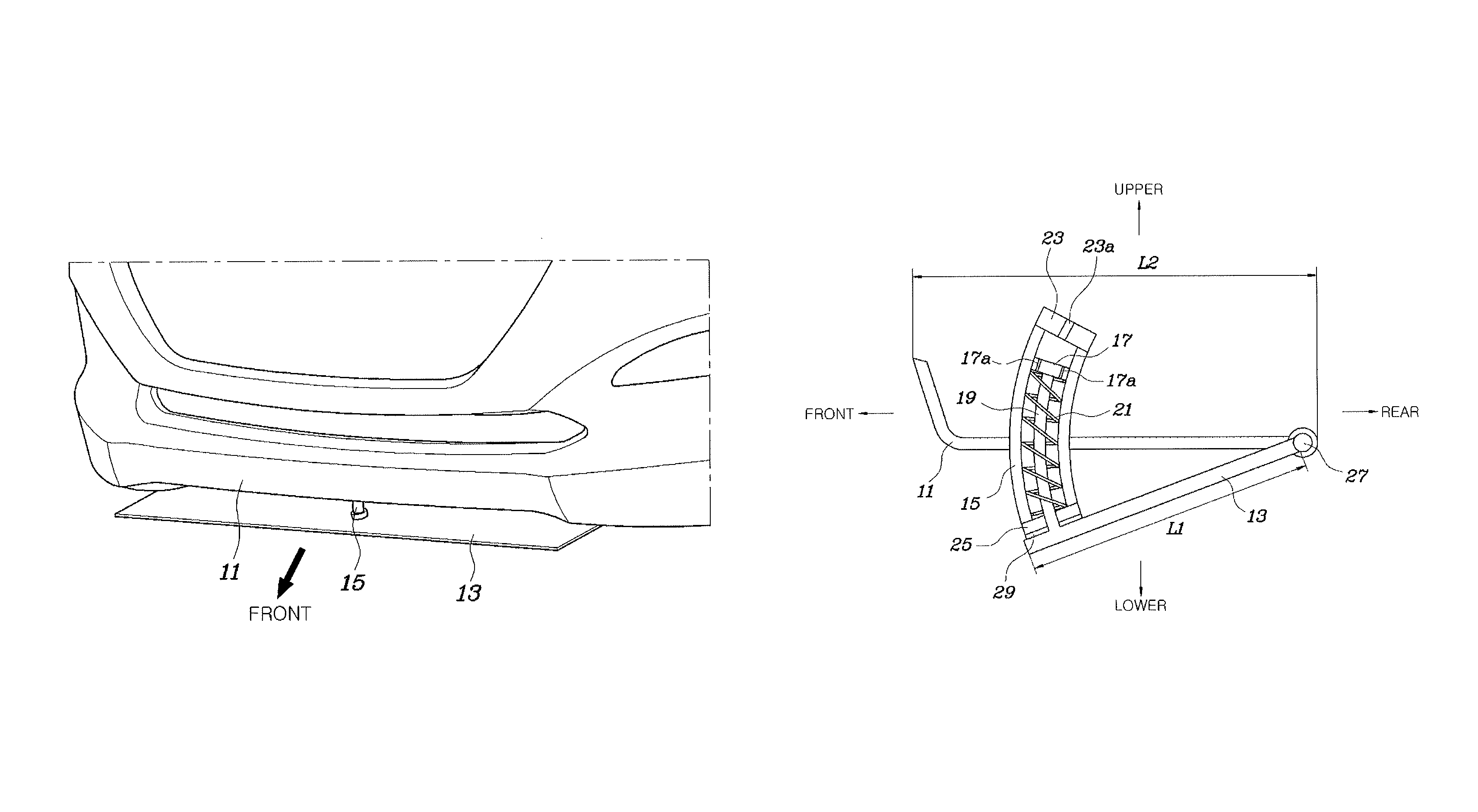
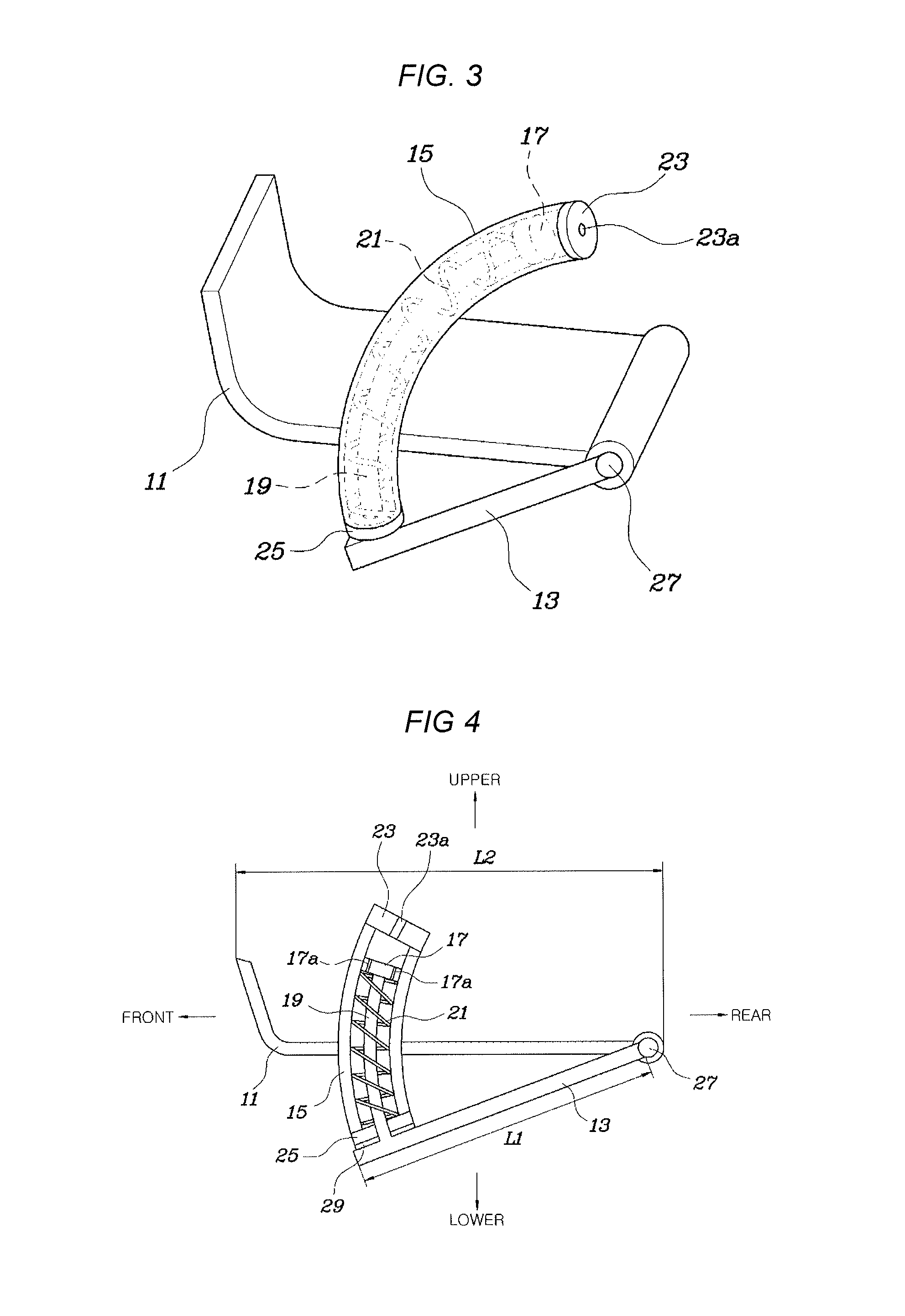
The present invention provides a front spoiler apparatus for a vehicle that can automatically adjust its protruding amount based on the vehicle's speed, and prevent damage to the spoiler when the vehicle travels on a road surface. This is achieved without the need for costly and heavy actuators, making the apparatus lighter, more fuel efficient, and more aesthetically appealing. Additionally, the front spoiler panel does not have any holes for air input, which improves its appearance and reduces noise vibration. The guide cylinder and guide rod are designed in an arch shape, and air passages are formed through the piston to absorb noise and vibration. A rubber packing is used to prevent impact and vibration, and a rubber packing is integrally connected to the lower stopper to absorb impact and vibration while the spoiler panel is in close contact with the bottom surface of the front bumper.

Problems solved by technology

However, according to the conventional art, the lower panel constructing a spoiler contacts repeatedly the obstacle on a road surface thereby to produce noise and cause breakage damage due to durability decreasing.
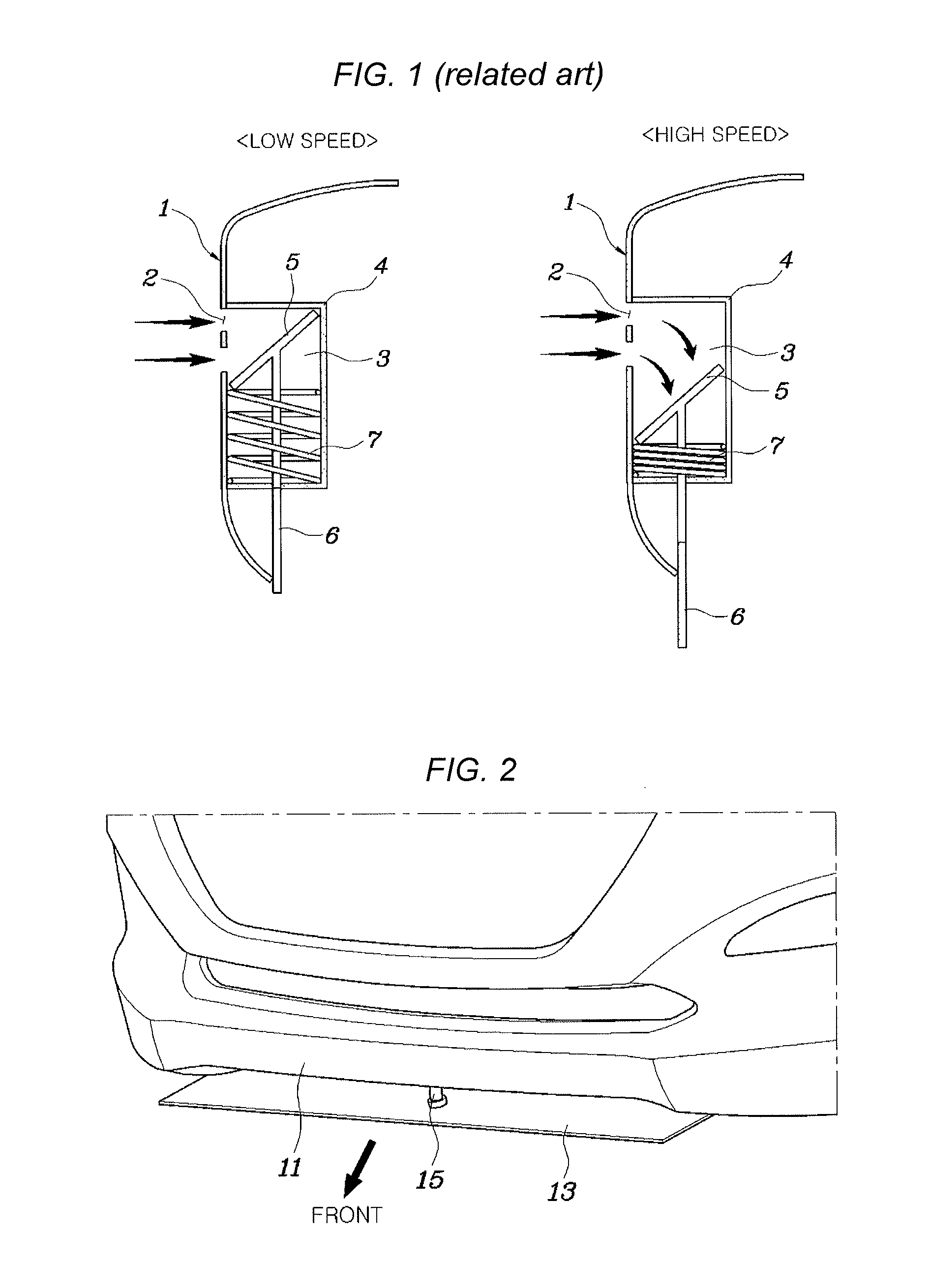
However, according to the conventional front spoiler apparatus as configured above, it needs actuators such as a controller, a motor, a gear and the like and thus its weight increases deteriorates fuel efficiency and increases cost.
However, according to the conventional configuration as described above, the air input hole 2 is formed through the front bumper 1 and thus its aesthetic appearance is poor and there is a limitation to designing the front bumper 1 due to the air input hole 2.
At this time, there is no configuration for damping the vibration of the spoiler 6 in the conventional apparatus and thus the vibration of the spoiler 6 is transmitted through the support wall 4, thereby producing vibration noise.
Additionally, according to a conventional front spoiler apparatus, the spoiler 6 that is protruded to a lower side of a bumper returns rapidly while it moves upward through the elastic force of the spring 7 when a vehicle brakes suddenly while the vehicle travels at a high speed, and at this time the water pressure plate 5 of the spoiler 6 collides directly and strongly with the support wall 4, thereby producing noise and weakening durability.

Method used


Image

  • Front spoiler apparatus for vehicle
  • Front spoiler apparatus for vehicle
  • Front spoiler apparatus for vehicle

Examples


Embodiment Construction

[0035]Reference will now be made in detail to various embodiments of the present invention(s), examples of which are illustrated in the accompanying drawings and described below. While the invention(s) will be described in conjunction with exemplary embodiments, it will be understood that present description is not intended to limit the invention(s) to those exemplary embodiments. On the contrary, the invention(s) is / are intended to cover not only the exemplary embodiments, but also various alternatives, modifications, equivalents and other embodiments, which may be included within the spirit and scope of the invention as defined by the appended claims.

[0036]The terminology used herein is for the purpose of describing particular embodiments only and is not intended to be limiting of the invention. As used herein, the singular forms “a,”“an” and “the” are intended to include the plural forms as well, unless the context clearly indicates otherwise. It will be further understood that t...


PUM


Abstract

A front spoiler apparatus for a vehicle may include a spoiler panel, a rear end of which is rotatably connected to a bottom surface of a front bumper such that the spoiler panel is rotatable up / downward, a guide cylinder that is arranged to pass through the bottom surface of the front bumper to be fixed to the front bumper, a piston that is arranged within the guide cylinder and moves along the guide cylinder, a guide rod that is arranged to connect a front end of the spoiler panel and the piston, and an elastic member that is arranged within the guide cylinder and provides elastic force to rotate the spoiler panel toward the front bumper.

Description

CROSS REFERENCE TO RELATED APPLICATION[0001]The present application claims priority of Korean Patent Application Number 10-2014-0053483 filed on May 2, 2014, the entire contents of which application are incorporated herein for all purposes by this reference.BACKGROUND OF INVENTION[0002]1. Field of Invention[0003]The present invention relates to a front spoiler apparatus for a vehicle, and more particularly, to a front spoiler apparatus for a vehicle of which the protruding amount is varied actively in line with a vehicle speed.[0004]2. Description of Related Art[0005]Generally, a vehicle receives air-resistant force through collision with atmospheric air while it travels wherein the air-resistant force is classified as a drag and lift. The drag is the resistant force that acts opposite to the motion direction of a vehicle body that is collided directly with air while it travels and the lift is the force that lifts a vehicle body by pressure difference created between top and bottom ...

Claims


Application Information

Patent Timeline
IPC IPC(8): B62D35/00
CPCB62D35/005Y02T10/82B62D37/02
Inventor KIM, HAK LIMKIM, HYUN GYUNGSHIN, JUN SIK
Owner HYUNDAI MOTOR CO LTD
Learn More