Wing extension control surface

a control surface and wing technology, applied in the direction of rotor aircraft, vertical landing/take-off aircraft, vehicles, etc., can solve the problems of little application of tilt-wing configuration, conversion from helicopter to airplane mode, and the type of tilt-rotor aircra

Active Publication Date: 2015-08-11
TEXTRON INNOVATIONS
View PDF11 Cites 51 Cited by
  • Summary
  • Abstract
  • Description
  • Claims
  • Application Information

AI Technical Summary

Problems solved by technology

But, a tilt-wing configuration has found very little application because conversion from helicopter to airplane mode, and vice-versa, is difficult and inefficient.
This type of tiltrotor aircraft has found little application because of the difficulties associated with incorporating a partially rotatable wing in lieu of having a rigid whole wing.

Method used


Image

  • Wing extension control surface
  • Wing extension control surface
  • Wing extension control surface

Examples


Embodiment Construction

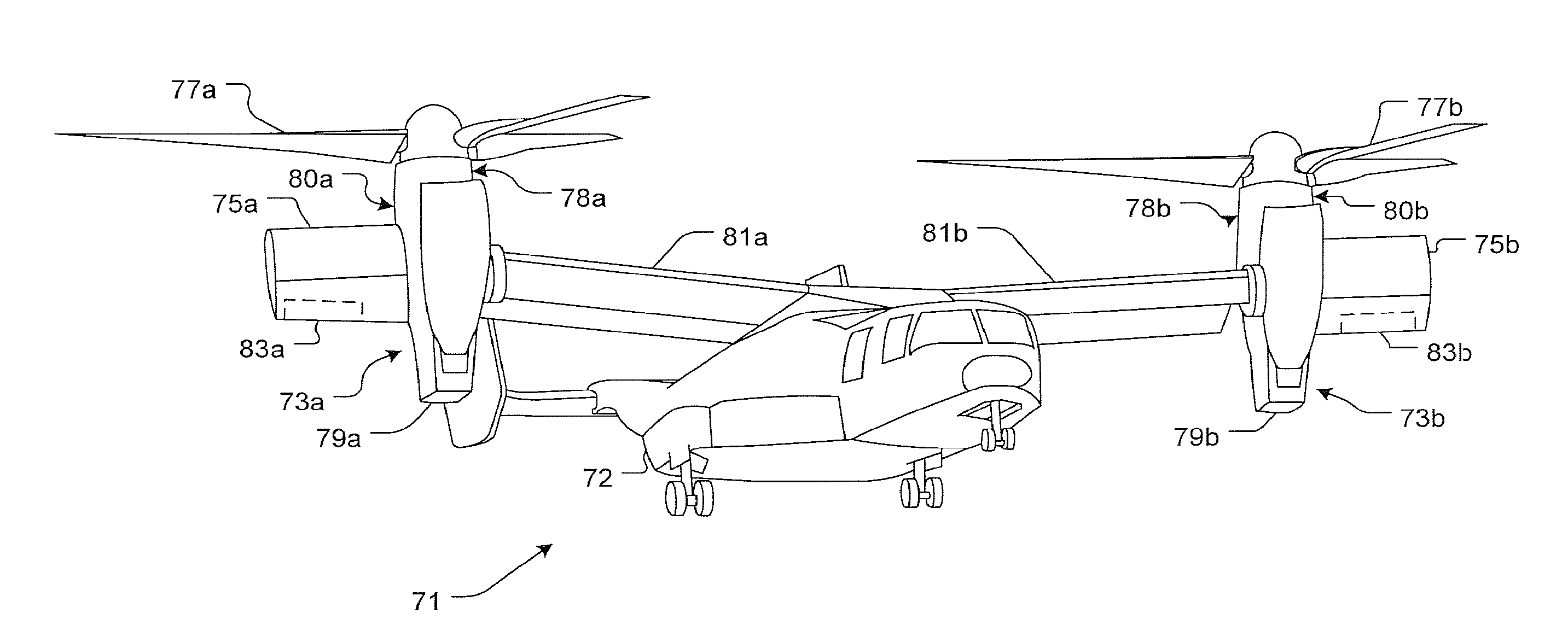
[0019]The present application discloses substantial improvements in the field of helicopters and other rotorcraft. The present application describes a rotatable wing extension that pivotally attaches to the outboard section of the aircraft's nacelle. The wing extension creates additional yaw control during helicopter mode and increases lift during airplane mode. The additional lift enables the aircraft to increase payload capacity.

[0020]Illustrative embodiments are described below. In the interest of clarity, not all features of an actual implementation are described in this specification. It will of course be appreciated that in the development of any such actual embodiment, numerous implementation-specific decisions will be made to achieve the developer's specific goals, such as compliance with system-related and business-related constraints, which will vary from one implementation to another. Moreover, it will be appreciated that such a development effort might be complex and tim...


PUM


Abstract

A tiltrotor aircraft includes a rotatable nacelle that supports a rotor assembly and is pivotally attached to the air-craft's fuselage. A wing extension attaches to an outboard section of the nacelle. The wing extension provides additional yaw control during helicopter mode and additional lift during airplane mode. A method for controlling at least a portion of yaw movement includes positioning the rotor assembly in helicopter mode, creating rotor wash with the rotor assembly, and pivotally rotating the wing extension in the rotor wash.

Description

TECHNICAL FIELD[0001]The present application relates to wing extensions, and more particularly to a wing extension for a tiltrotor aircraft.DESCRIPTION OF THE PRIOR ART[0002]Tiltrotor and tiltwing aircraft operate in two modes: helicopter and airplane modes. In helicopter mode, the aircraft's rotors are positioned to create lift, thereby enabling the aircraft to achieve vertical take-off and landing. In this configuration, the aircraft is essentially a helicopter. As the aircraft gains speed, the rotors are slowly tilted forward, eventually transitioning to airplane mode. In airplane mode, the aircraft is essentially a turboprop aircraft.[0003]A typical tiltwing aircraft transitions between helicopter and airplane mode by pivotally moving the aircraft's entire wing span to a position substantially perpendicular and horizontal to the aircraft's fuselage, respectively. The tiltwing configuration is ideal for reducing rotor wash interaction with the aircraft's wing during helicopter mo...

Claims


Application Information

Patent Timeline
Patent Type & Authority Patents(United States)
IPC IPC(8): B64C27/28B64C29/00
CPCB64C29/0033
Inventor COLLINS, BOBSTAMPS, FRANK B.CORRIGAN, III, JOHN J.DREIER, MARK E.
Owner TEXTRON INNOVATIONS
Why Eureka
Try Eureka