HRSG for fluidized gasification

a fluidized bed and gasification technology, applied in the direction of combustible gas production, sustainable manufacturing/processing, lighting and heating apparatus, etc., can solve the problems of local overheating and damage of the tube sheet and the fire tube assembly, and affecting the gasification efficiency of the fluidized bed. achieve the effect of reducing the abrasion of metal parts

Active Publication Date: 2015-08-11
GAS TECH INST
View PDF14 Cites 35 Cited by
  • Summary
  • Abstract
  • Description
  • Claims
  • Application Information

AI Technical Summary

Benefits of technology

[0008]The first technical problem to be solved by the present invention is to provide an HRSG for fluidized bed coal gasification. The inventive HRSG reduces abrasion of metal portions of the fire-tube boiler of the superheater, the low temperature evaporator, and the economizer caused by ashes in the raw syngas.
[0009]The second technical problem to be solved by the present invention is to provide an HRSG for fluidized bed coal gasification, which can avoid local overheating and overburning of the tube sheet and the fire tube assembly of the high temperature evaporator due to gases and steam produced by desalted water floating to the top of the fire tube assembly of the high temperature evaporator.
[0010]The third technical problem to be solved by the present invention is to provide an HRSG for fluidized bed coal gasification, which can save spaces occupied by the high temperature evaporator, superheater, low temperature evaporator, and economizer and avoid complicated and troublesome repairs and maintenances.

Problems solved by technology

However, due to the high contents of coal ashes and semi-cokes in the syngas produced from fluidized bed coal gasification, the fire-tube boiler inlets of the superheater, the low temperature evaporator and the economizer are bombarded by these coal ashes and semi-cokes, resulting in abrasion thereon, pipe leakage and system shutdown.
Further, because the existing high temperature evaporator is a vertically straight fire-tube boiler, gases and part of the steam produced by desalted water float to the top of the fire tube assembly of the high temperature evaporator, which will result in local overheating and damage of the tube sheet and the fire tube assembly.
Also, conventionally, the high temperature evaporator, superheater, low temperature evaporator, and economizer are separately located, and occupy a large space, making it difficult and troublesome to maintain to repair.
In the prior art, the economizer is made of carbon steel, which will result in dew corrosion on the outer surface of the steel pipe because the temperature in the economizer is not high enough.

Method used


Image

  • HRSG for fluidized gasification
  • HRSG for fluidized gasification
  • HRSG for fluidized gasification

Examples


Embodiment Construction

[0028]An embodiment according to the present invention is provided below in conjunction with the accompanying figures.

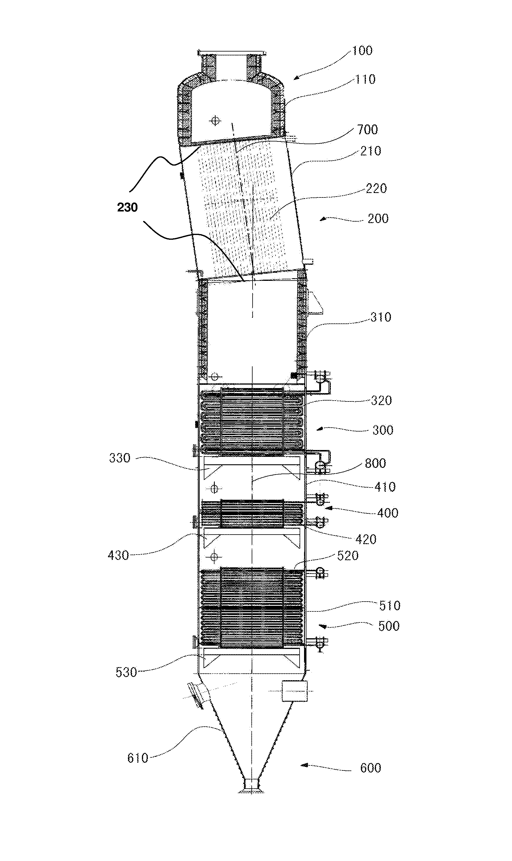
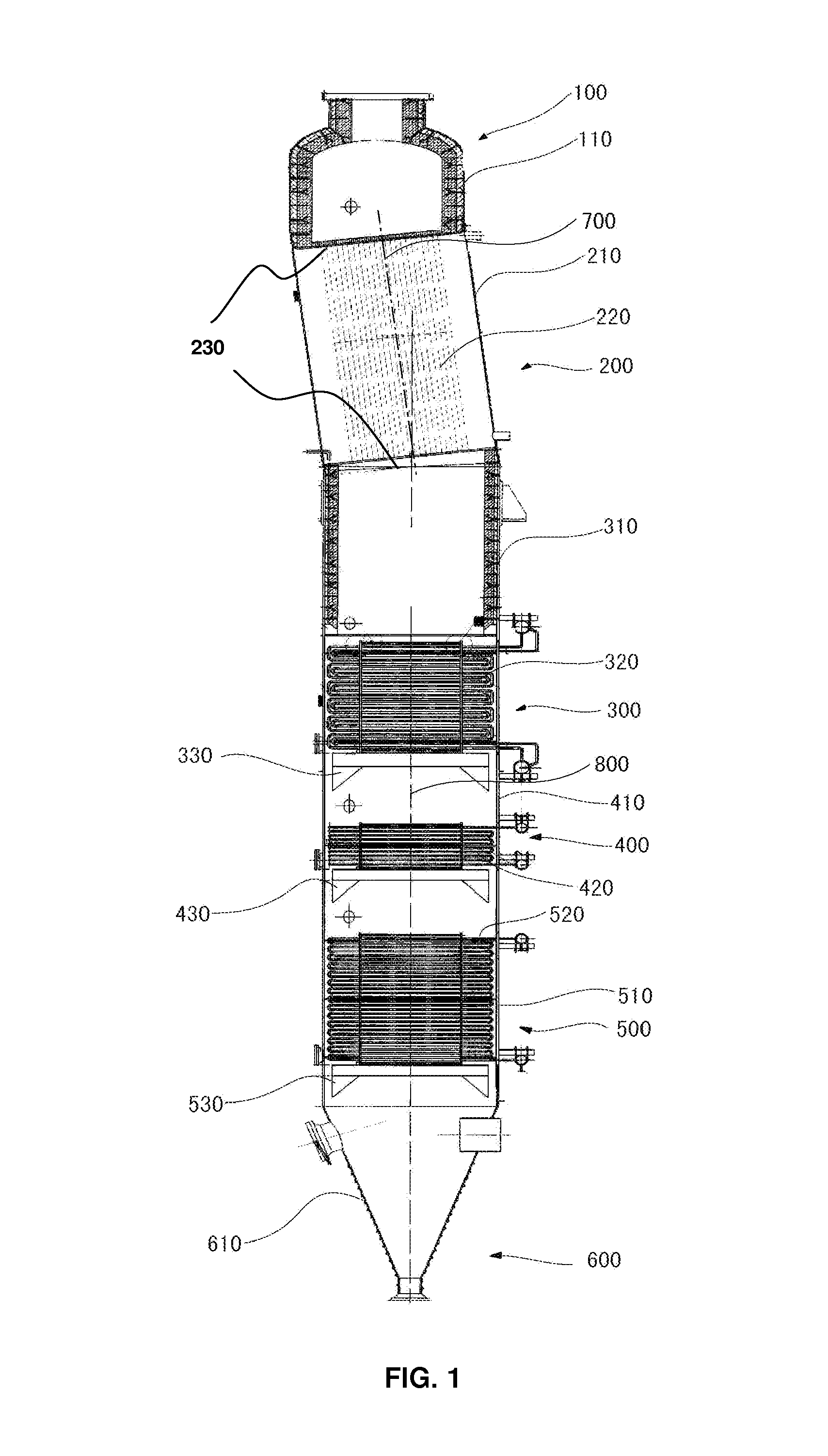
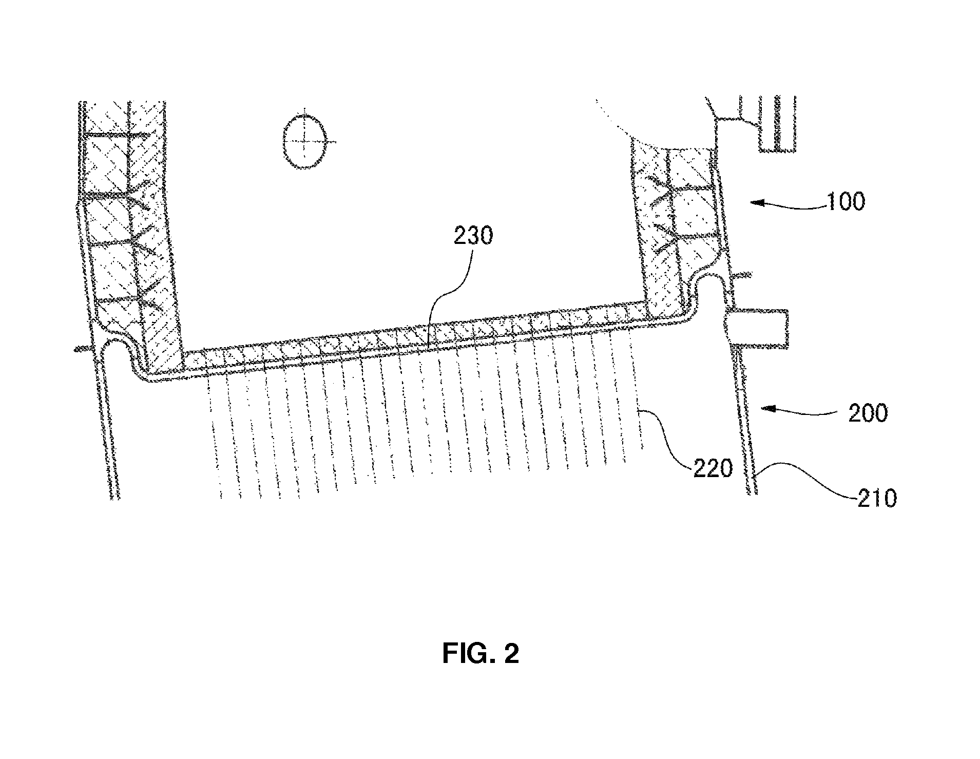
[0029]As shown in FIG. 1, an HRSG for fluidized bed coal gasification according to the present invention comprises six sections, i.e. an HRSG upper inlet 100, a high temperature evaporator 200, a superheater 300, a low temperature evaporator 400, an economizer 500 and an HRSG lower outlet 600, forming a combined structure. Specifically, the HRSG upper inlet 100 is located on the top of the HRSG, the high temperature evaporator 200 is arranged below the HRSG upper inlet 100, the superheater 300 is located below the high temperature evaporator 200, the low temperature evaporator 400 is located below the superheater 300, the economizer 500 is located below the low temperature evaporator 400, the HRSG lower outlet 600 is located at the bottom of the HRSG. The superheater 300, the low temperature evaporator 400, and the economizer 500 have a water-tube structure and the h...


PUM

PropertyMeasurementUnit
angleaaaaaaaaaa
speedaaaaaaaaaa
speedaaaaaaaaaa

Abstract

An HRSG for fluidized bed gasification comprises a high temperature evaporator (200), a superheater (300), a low temperature evaporator (400), and an economizer (500) connected in series. The superheater (300), the low temperature evaporator (400) and the economizer (500) have a water-tube structure, and the high temperature evaporator (200) has a fire-tube structure. The HRSG of the present invention allows efficient heat recovery from the raw syngas of a fluidized bed coal gasifier, while avoids or reduces the corrosion of and damage to the components of the HRSG caused by high-speed ash particles in the syngas.

Description

FIELD OF THE INVENTION[0001]This invention relates to a Heat Recovery Steam Generator (hereafter “HRSG”), and in particular, to an HRSG for fluidized bed coal gasification.BACKGROUND OF THE INVENTION[0002]An HRSG is a heat exchanger to produce steam utilizing waste heat as heat source, and it is not only used for cooling, but also for providing waste heat to produce steam. Structurally, an HRSG may be classified as a shell-and-tube type, or a gas-pass type depending on whether the high temperature gas flows inside or outside a heat exchange tube. In a shell-and-tube HRSG, also called fire-tube HRSG, flue gas flows inside a heat exchange tube and water flows in a shell outside the heat exchange tube. Heat is transferred to water outside the tube through the tube wall. Generally, a shell-and-tube HRSG does not comprise a superheater section or an economizer section because water is simply evaporated. A large-sized shell-and-tube HRSG comprises a steam drum, a downcomer and a riser, wh...

Claims


Application Information

Patent Timeline
Patent Type & Authority Patents(United States)
IPC IPC(8): F01K13/02F01K23/06F22B9/00F02B59/00C10J3/48F22B11/02F28F9/02F28D7/00F28F21/08F28D7/16F28D7/08
CPCC10J3/482F01K23/067F22B11/02F28F9/0219F28F9/0241F28D7/0066F28D7/08F28D7/16F28F21/08Y02E20/18C10J2300/1687Y02P20/129Y02P20/10Y02T10/12
Inventor GU, MINGHAISUN, SONGLIANGLUO, GUANGLIANG
Owner GAS TECH INST
Why Eureka
Try Eureka