Airflow pattern for spiral ovens

a spiral oven and airflow pattern technology, applied in the field of spiral ovens, can solve the problems of increasing the floor space requirements, the cost of increasing the heat transfer system needed to cook the product, and the problem of spiral ovens that are far more difficult to solve, so as to reduce or eliminate the temperature difference between products, the effect of quick change of directions and low cos

Active Publication Date: 2015-08-18
MARLEN INT
View PDF14 Cites 7 Cited by
  • Summary
  • Abstract
  • Description
  • Claims
  • Application Information

AI Technical Summary

Benefits of technology

[0011]Fan speed can be controlled to increase or decrease the airflow patterns within the spiral oven. The forward / reversing fan can be prevented from running at its maximum speed when operating in the reverse direction and a braking resistor can be used so that the fan can quickly changeover between the full-forward and full-reverse directions. Because of the reversing airflow pattern, the product cooks more evenly across the cook belt than with the prior art methods.
[0012]An improved spiral oven made according to this invention has a forward / reversing fan located in an upper portion of the spiral oven and means for distributing the air produced by the fan within a cooking chamber of the spiral oven. The fan alternates between a first direction of rotation and a second direction of rotation during a timed cycle “T”. The first direction of rotation may represent a greater proportion of the timed cycle T than the second direction, or the proportion of time between the two directions may be substantially even. Additionally, the first or second direction of rotation can begin the cycle. Further, the cycle can begin at the halfway point (or some other proportion of) the forward or reverse timed cycle. The fan velocity may be varied so that the speed of the airflow in the first direction of rotation is different from the speed of the airflow in the second direction of rotation. A braking resistor in communication with the fan motor allows the fan to quickly change directions, while a programmable delay limits adjustments to the heat output control method until temperature variations caused by alternating between the first and second directions of rotation have stabilized.
[0013]Objects of this invention are to (1) provide an airflow pattern within the cook chamber of a spiral oven that accounts for the unbalanced loading of product as the cook belt traverses bends within the spiral oven; (2) transfer the appropriate amount of heat to each product across the cook belt regardless of where the product is located on the belt; (3) provide uniformity of color development of product across the cook belt without degrading the CPET tray that each product may be contained within; (4) reduce or eliminate temperature differences between product located on the inside, middle and outside portions of the cook belt; and (5) provide a system and method of reversing airflow that existing ovens can take advantage of through relatively low cost retrofits.

Problems solved by technology

Consistently creating a final, cooked product appearance that resembles one typically created in a residential oven has proven to be a far more difficult problem to solve in spiral ovens than it is in linear ovens.
Impingement cooking produces an acceptable “browned” appearance but comes at the price of increased floor space requirements.
However, compressing the cook belt creates problems for the heat transfer system needed to cook the product.
All prior art spiral ovens are designed to provide a substantially uniform airflow across the cook belt because conventional wisdom in the art of spiral oven design holds that a non-uniform airflow across the belt is not desirable and must be avoided.

Method used


Image

  • Airflow pattern for spiral ovens
  • Airflow pattern for spiral ovens
  • Airflow pattern for spiral ovens

Examples


Embodiment Construction

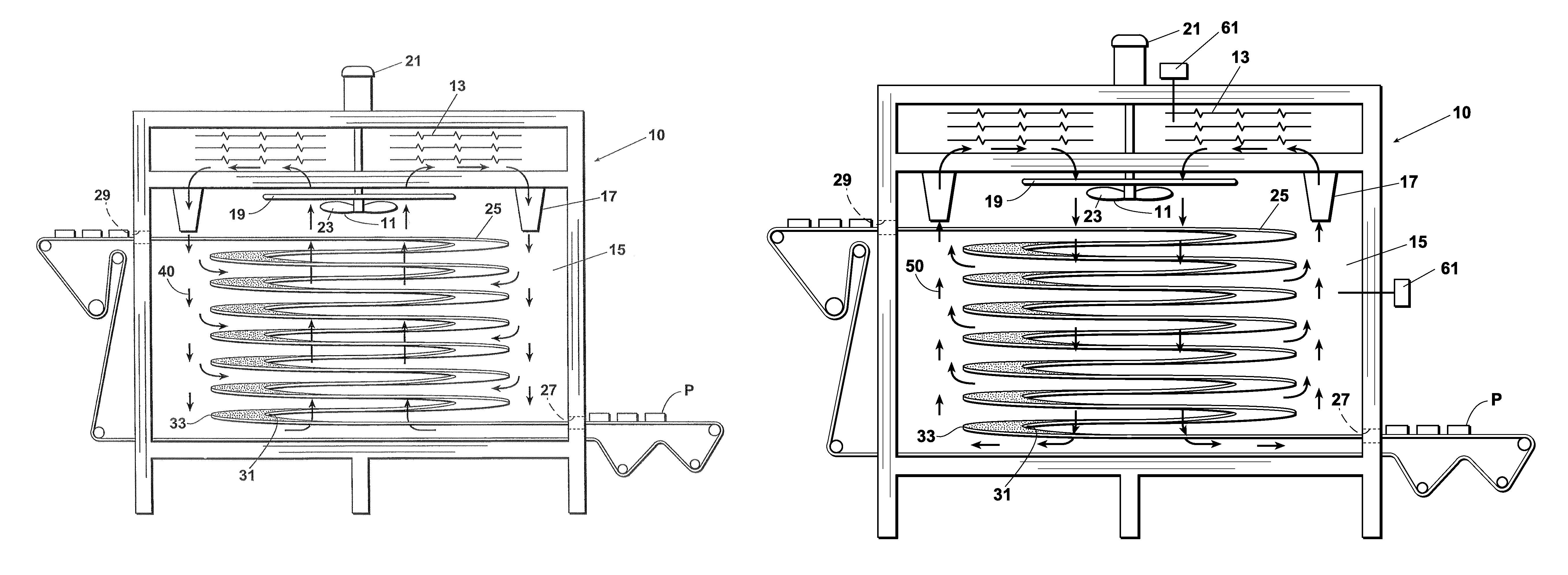
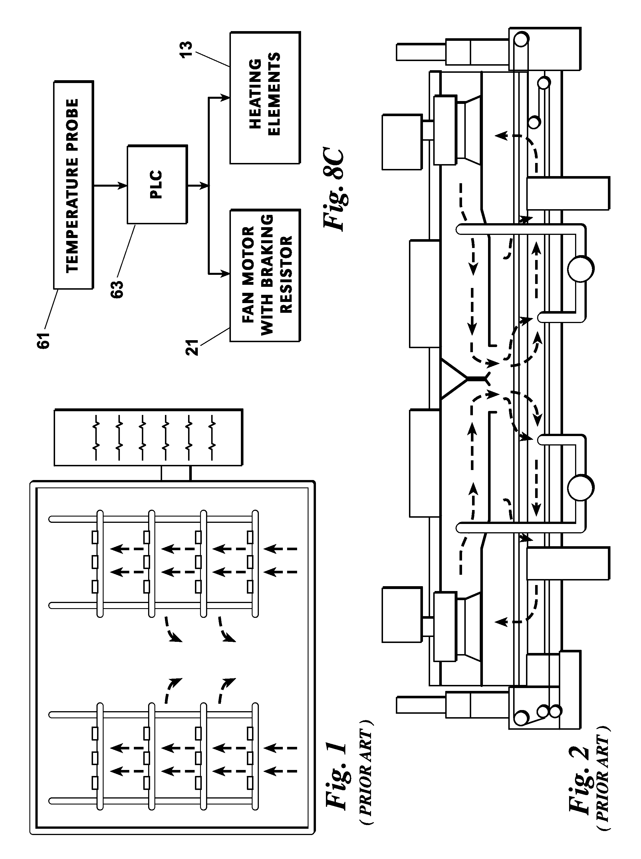
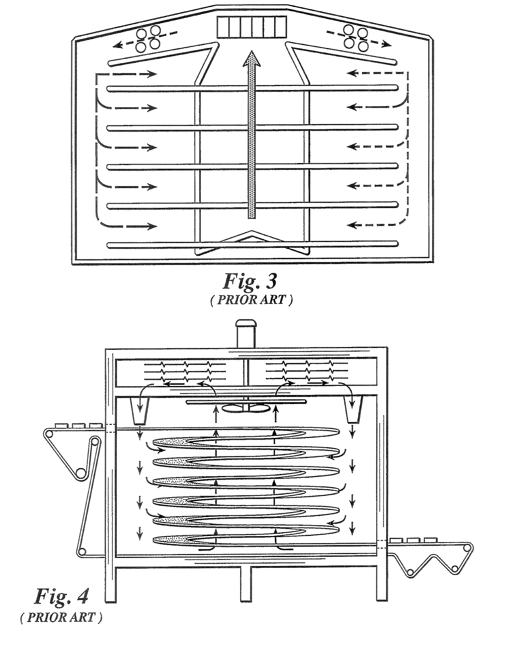
[0025]A spiral oven made according to this invention creates a controlled airflow pattern that better reflects the heat transfer demands of the product being cooked in the oven. Because the product to be cooked is loaded uniformly across the width of the cook belt, prior art spiral ovens (see e.g. FIGS. 1 to 4) are designed to provide a unidirectional airflow pattern within the cooking chamber and, therefore, a substantially uniform airflow across the belt. The width of the cook belt in most commercial spiral ovens ranges between 12 and 42 inches.

[0026]Regardless of the width of the cook belt, a loading pattern must be determined relative to the size of the tray in which the product or meal to be cooked is placed. Consider a 40-inch wide cook belt loaded with trays that are 7 inches wide, 10 inches long, and 2 inches deep (see FIG. 5). The trays are typically CPET trays used for microwaveable-ready meals. If the cook belt is loaded four trays across, with the trays arranged short si...


PUM


Abstract

An improved spiral oven and method for its use includes the step of using a forward / reversing fan to produce a first airflow and a second inverted airflow in the cooking chamber. The proportion of time each airflow occurs may be unbalanced within an oven residence time or cook cycle, and either airflow may begin the cycle. In addition, the fan velocity may vary so that the speed of the first airflow is different from the speed of the second airflow. A braking resistor allows the fan to quickly changeover between full-forward and full-reverse directions, while a programmable delay limits adjustments to the heat output control method until temperature variations caused by alternating between the first direction of rotation and the second direction of rotation have stabilized. Because of the reversing airflow pattern, the product cooks more evenly across the cook belt.

Description

CROSS-REFERENCE TO CO-PENDING APPLICATIONS[0001]This application is a continuation-in-part of U.S. patent application Ser. No. 13 / 044,370 and claims the benefit of that application.FIELD OF THE INVENTION[0002]This invention relates generally to spiral ovens which are used to cook large quantities of food in commercial food preparation processes. More particularly, the invention relates to apparatuses and methods to create airflow patterns within the cook chamber of a spiral oven in order to effectively and uniformly heat the product being cooked and produce a desired final cooked product appearance across the cook belt.BACKGROUND OF THE INVENTION[0003]Consistently creating a final, cooked product appearance that resembles one typically created in a residential oven has proven to be a far more difficult problem to solve in spiral ovens than it is in linear ovens. Linear ovens cook food using an airflow process known as impingement cooking. In impingement cooking, hot vertical airflow...

Claims


Application Information

Patent Timeline
Patent Type & Authority Patents(United States)
IPC IPC(8): F24C15/32A21B1/48A21B1/40A21B1/26
CPCA21B1/26F24C15/322A21B1/48A21B1/40A23L5/15A23V2002/00
Inventor HOWARD, DAVIDLAUR, AUSTEN
Owner MARLEN INT
Why Eureka
Try Eureka