Screw thread with flattened peaks

a technology of threads and peaks, which is applied in the field of bone fasteners, can solve the problems of the thread head of the fastener being able to tilt and jam within the threaded portion of the implant hole, the edge and groove of the thread, and the damage of the thread head

Active Publication Date: 2015-08-18
STRYKER EURO OPERATIONS HLDG LLC
View PDF15 Cites 63 Cited by
  • Summary
  • Abstract
  • Description
  • Claims
  • Application Information

AI Technical Summary

Problems solved by technology

During the screwing-in operation of the bone fastener head into the implant, the thread of a head of the fastener can tilt and jam within the threaded portion of the implant hole.
Thereby, the flanks and peaks of the threaded head and the threaded hole may get damaged.
Moreover, splinters from the bone drilling as well as other materials like parts of human tissue can contaminate the edges and grooves of the threads, whereby the thread of the threaded head and the internal thread of the hole of the implant can jam.

Method used


Image

  • Screw thread with flattened peaks
  • Screw thread with flattened peaks
  • Screw thread with flattened peaks

Examples


Embodiment Construction

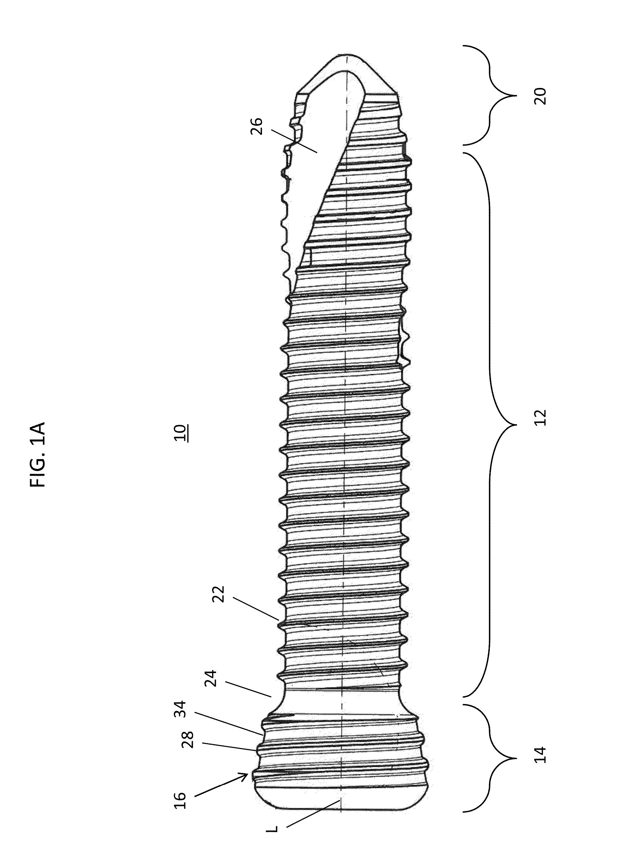
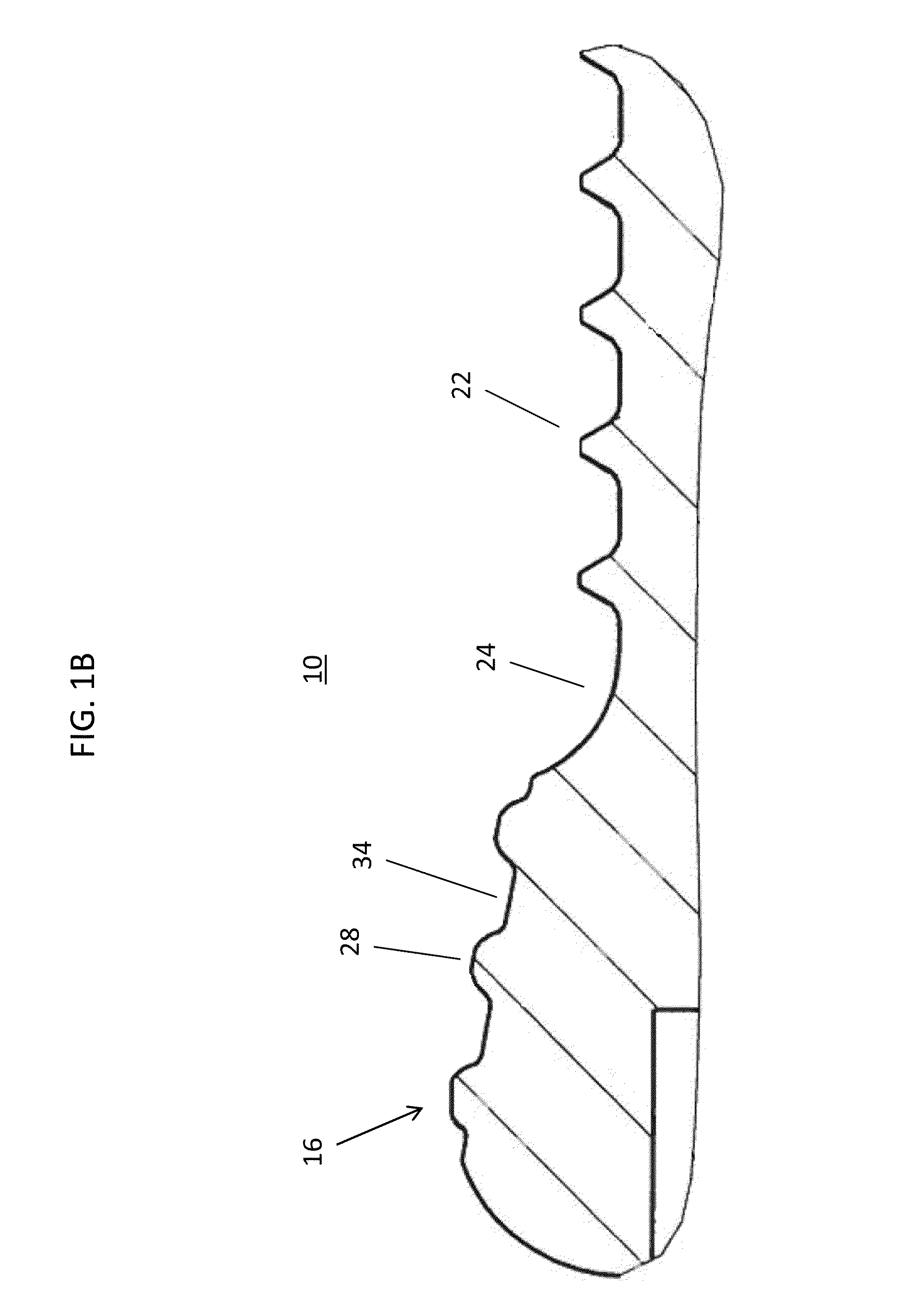
[0021]Referring to FIGS. 1A-B, there are shown side view and sectional views of one embodiment of a bone fastener according to an aspect of the invention. The bone fastener is in the form of a bone screw 10 for use as a locking screw in orthopedic surgery for fixing an implant (shown in FIGS. 4, 8) to bone. The bone screw 10 includes a shaft 12 configured to engage bone and a head 14 having a thread 16 on an outer surface to engage the implant. The bone screw 10 has a longitudinal axis L. The head 14 is provided at a distal side of the shaft 12 and a tip 20 is provided at a proximal side of the shaft 12. The tip 20 may be formed as a cone having an opening angle of, for example, 60° to 120°.

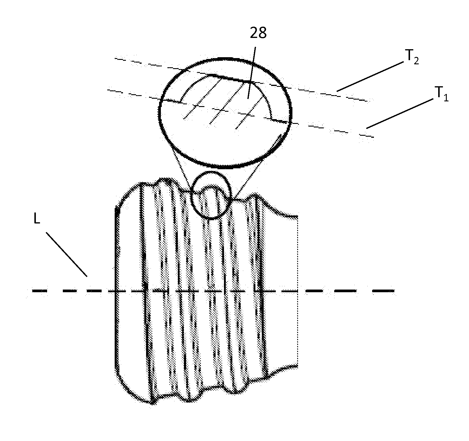
[0022]Further, as illustrated in FIGS. 1A-B, the shaft has a threaded portion 22. Trapezoidally shaped peaks of the threaded portion 22 are separated by valleys having a planar profile in cross section. The threaded portion 22 of the shaft may have a constant thread pitch. The threaded portion 22...


PUM


Abstract

A bone fastener for use in orthopedic surgery for fixing an implant to bone has a threaded or unthreaded shaft configured to engage bone and a head having a thread on an outer surface to engage the implant. The thread on the head of the fastener has a profile in cross section that includes arcuate peaks with a flat on the outer surface of the peak.

Description

FIELD OF THE INVENTION[0001]The present disclosure generally relates to a bone fastener such as a bone screw or bone peg for use in orthopedic surgery, preferably for fixing an implant such as a bone plate to bone.BACKGROUND OF THE INVENTION[0002]Bone screws are available in a plurality of variations for different applications. Bone screws which can be secured to a bone plate or a similar implant are also known as locking screws. For locking the bone screw to the bone plate, a head of the bone screw is provided with a thread that mates with a corresponding thread on an inner surface of a plate hole.[0003]U.S. Patent Publication Nos. 2005 / 0277937 and 2009 / 0192550 relate to a typical locking screw which is intended to be secured to a bone plate. The head of the bone screw has a spherical shape and a thread with V-shaped ridges. The thread of the head is a double lead thread which mates with an internal thread of a plate hole. The ridges of the thread provided in the plate hole have a ...

Claims


Application Information

Patent Timeline
Patent Type & Authority Patents(United States)
IPC IPC(8): A61B17/04A61B17/80A61F2/08A61B17/86
CPCA61B17/8057A61B17/8605
Inventor HAINARD, NICOLAS
Owner STRYKER EURO OPERATIONS HLDG LLC
Why Eureka
Try Eureka