Pump having an axial balancing device

Active Publication Date: 2015-08-18
ARIANEGRP SAS
View PDF14 Cites 0 Cited by
  • Summary
  • Abstract
  • Description
  • Claims
  • Application Information

AI Technical Summary

Benefits of technology

[0022]The aim of the invention is to rectify the above disadvantages by defining a pump comprising a stator, a rotor comprising at least one impeller, and an axial balancing device arranged on at least one impeller of the rotor in which (or especially, though not exclusively, having a wall, in particular a front wall, against which) a fluid duct passes, said device comprising for each involved wheel in this device a balancing chamber extending between a wall of said involved wheel and the stator, and a passage arranged between said involved wheel and t

Problems solved by technology

Due to the arrangement of the passage with an annular chamber placed between two nozzles, the jet of fluid passes through and circulates in the

Method used


Image

  • Pump having an axial balancing device
  • Pump having an axial balancing device
  • Pump having an axial balancing device

Examples


first embodiment

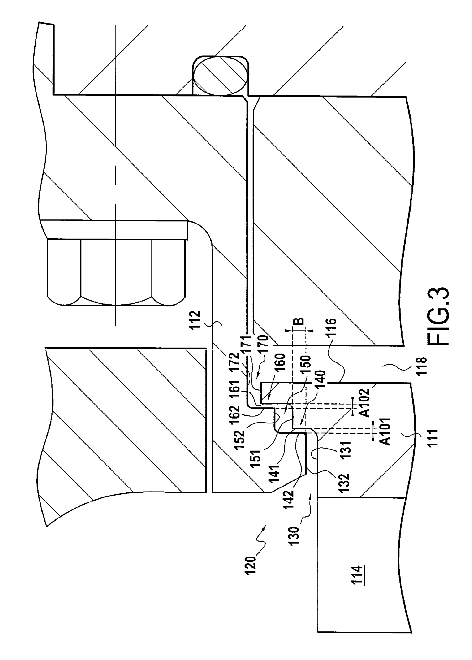
[0050]The operation of a pump axial balancing device, in the invention, will now be described in reference to FIG. 3.

[0051]FIG. 3 is a partial section of a pump overall similar to that presented in FIG. 1, specifically a single-stage pump comprising a wheel 111 of open type. However, the balancing device of the pump of FIG. 3 is different to that of the pump of FIG. 1.

[0052]The pump illustrated in FIG. 3 comprises a rotor 114 and a stator 112, and a thrust balancing device comprising especially a fluid passage 120 formed between the rotor 114 and the stator 112.

[0053]In the pump of FIG. 3, the thrust device is arranged on the rear wall of the impeller. It is understood of course that in general the thrust device can be arranged also just as easily on a rear wall of the wheel 111 as on a front wall of the latter.

[0054]Upstream to the side of the fluid duct, the passage 120 comprises an upstream axial part 130 extending between two substantially cylindrical walls 131,132 of circular s...

second embodiment

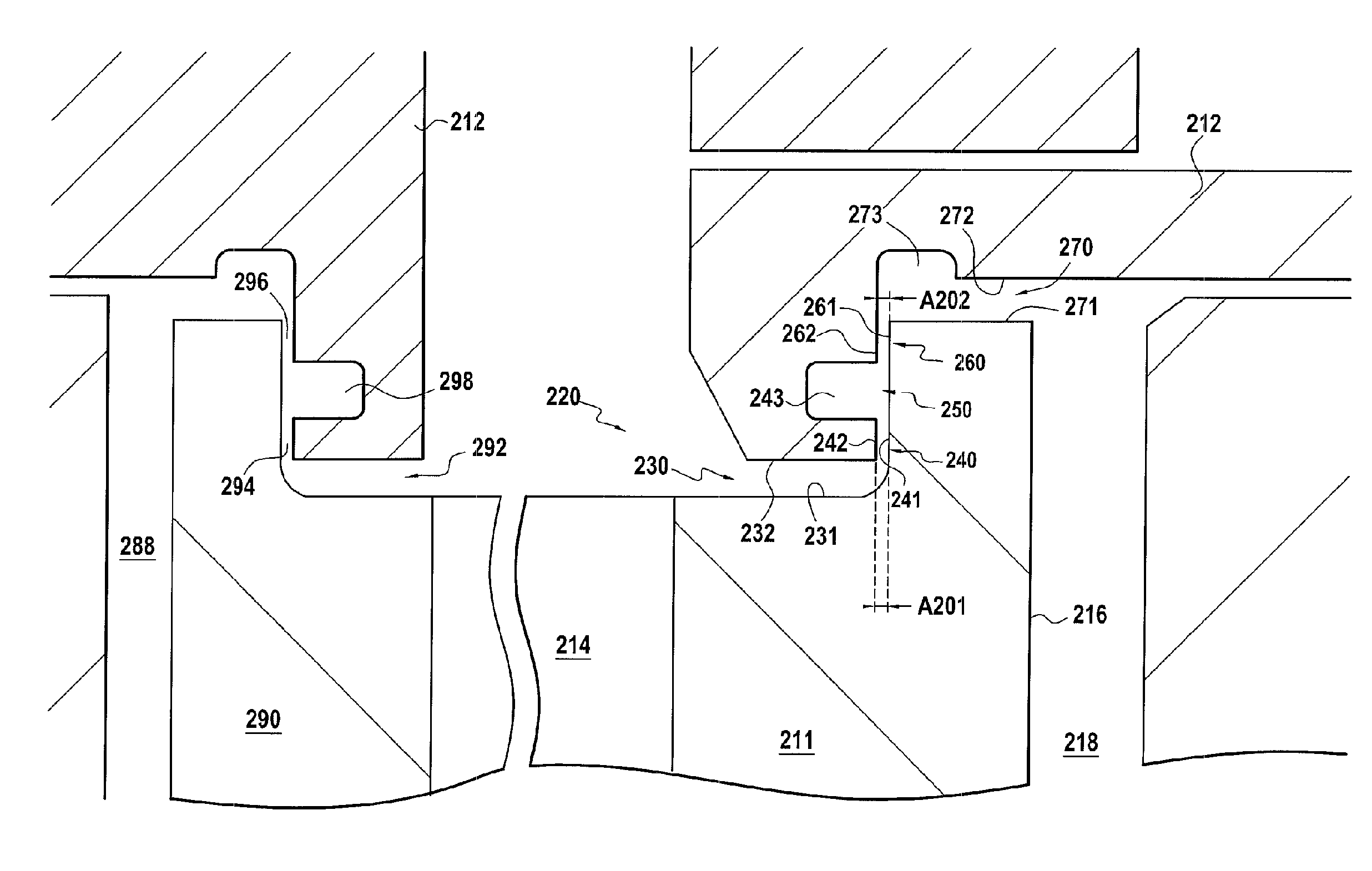
[0065]In reference to FIG. 4, a device in a centrifuging pump in the invention will now be described.

[0066]In this embodiment, at least one involved wheel in the axial balancing device, and in this case the impeller 211 is a closed, or flanged wheel, that is, closed by a cover 290 (or flange) to the front side of the vanes. To allow axial balancing in both directions along the axis of the pump, the axial balancing device is doubled, comprising first axial balancing means (especially a first passage 220) very similar to those presented in relation to FIG. 3, and second axial balancing means acting in the opposite direction, placed to the side of the cover.

[0067]In this embodiment, the different elements of the first axial balancing means, and especially the passage 220, are substantially the same as in the preceding embodiment and therefore will not be described in any further detail.

[0068]Concerning these first axial balancing means placed on the rear side of the wheel 211, the diff...

third embodiment

[0075]In reference to FIG. 5, a device in a centrifuging pump in the invention will now be described.

[0076]In this embodiment, the different elements of the axial balancing means, and especially the passage 320, are substantially the same as in the first embodiment and therefore will not be described in any further detail.

[0077]The particular feature of this third embodiment, relative to the first embodiment, is the absence of radial covering between the surfaces of the upstream 340 and downstream nozzles 360.

[0078]In this embodiment, the nozzles 340 and 360 actually have no radial covering. In fact, for each of these nozzles, the surfaces of the nozzles 341, 361; 342,362 respectively of the rotor and of the stator, comprise no part opposite along the axis of the pump. More precisely, with respect to the upstream nozzle 340, the surfaces 341 and 342 constituting this nozzle are separated by a radial distance C; with respect to the downstream nozzle 360, a radial distance D separates...


PUM


Abstract

The pump includes a stator and a rotor having an impeller in which a fluid duct passes. An axial balancing device arranged on this wheel includes a rear balancing chamber and a passage arranged between the wheel and the stator, enabling evacuation of fluid from the fluid duct to the balancing chamber. The pressure of fluid in the balancing chamber compensates the pressures exerted by the fluid on the rest of the rotor allowing axial balancing of the rotor. The passage includes an upstream nozzle and a downstream nozzle, as well as an intermediate annular chamber, arranged between walls of the wheel and of the stator, the intermediate chamber being arranged downstream of the upstream nozzle and upstream of the downstream nozzle.

Description

TECHNICAL FIELD[0001]The present invention relates to the axial balancing of a pump, in particular of a turbopump, especially a spatial motor.BACKGROUND[0002]It is known that the rotors of these machines often support considerable axial thrusts due to differences in pressure which arise on either side of the wheels, to variations in quantity of movement of fluids conveyed and, in some cases, to the weight or a fraction of the weight of the rotor itself.[0003]Because of this, pumps usually contain devices enabling compensation of the axial thrust exerted by the fluid on the rotor.[0004]These devices are likely to use all the surfaces on the front face (to the side of the vanes) and inversely on the rear face or back of the centrifuge wheels as surfaces on which fluid is to circulate to compensate the axial impingement of forces exerted on the rotating parts. As is known, the back of the last centrifuge wheel, for this reason known as the “balancing piston” is used more particularly f...

Claims


Application Information

Patent Timeline
IPC IPC(8): F04D29/042F04D29/22
CPCF04D29/042F04D29/2266
Inventor BOUFFLERT, SEBASTIENJUHEL, NICOLASFAYOLLE, PATRICELAFFITE, STEPHANE
Owner ARIANEGRP SAS
Why Eureka
Try Eureka