
Protective grid attachment

a protective grid and grid technology, applied in nuclear reactors, nuclear elements, greenhouse gas reduction, etc., can solve the problems of fuel assembly damage, debris to gyrate, chip and metal particles still remain hidden in the system,

Active Publication Date: 2011-09-08
WESTINGHOUSE ELECTRIC CORP
View PDF7 Cites 4 Cited by
  • Summary
  • Abstract
  • Description
  • Claims
  • Application Information

AI Technical Summary

Benefits of technology

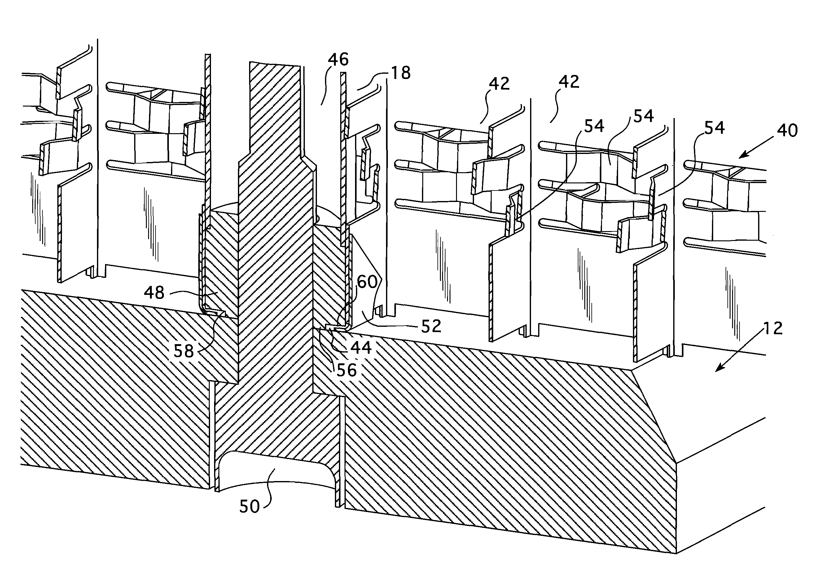
[0013]Preferably, the space between the end of the thimble tube and the spacer is large enough to accommodate any differential in thermal expansion between the spacer material, the nozzle material and the end of the thimble tube. Desirably, the lateral space between the end of the thimble tube and the spacer is approximately between 0.001 and 0.002 inches (0.003 and 0.005 cms.). The lateral clearance takes up the differential thermal expansion. In addition, a small axial clearance provides for a non-rigid connection so that the grid, spacer and bottom nozzle can move independently.

Problems solved by technology

Although elaborate procedures are carried out to help assure debris removal, experience shows that in spite of the safeguards used to effect such removal, some chips and metal particles still remain hidden in the system.
Fuel assembly damage due to debris trapped at the lower most grid has been noted in several reactors.
The damage consists of fuel rod tube perforations caused by fretting of the debris in contact with the exterior of the cladding tubes which sealably enclose the fissile material in the fuel rod.
The flowing coolant causes the debris to gyrate, which tends to cut through the cladding of the fuel rods.
Cracking has recently been experienced in the protective grid features which has led to fuel rod failures.
These failures have been determined to be caused by intergranular cracking, consistent with stress corrosion cracking.
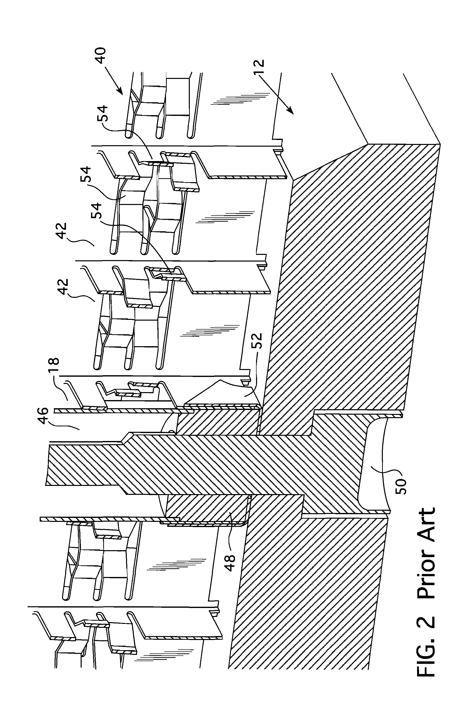
The stainless steel expands more during heat up than does the alloy-718, thus causing stresses in the protective grid, particularly near the attachment point.

Method used


Image

  • Protective grid attachment
  • Protective grid attachment
  • Protective grid attachment

Examples


Embodiment Construction

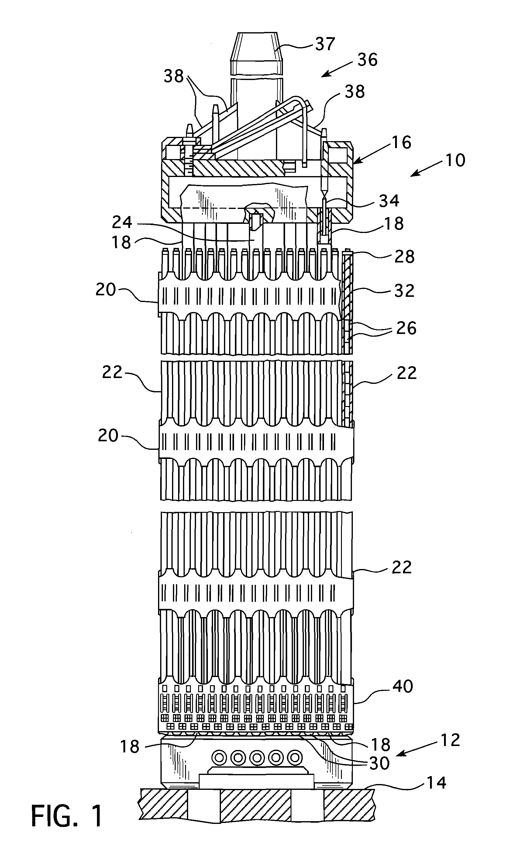
[0018]Referring now to the drawings and particularly to FIG. 1, there is shown an elevational view of a fuel assembly, represented in vertically shortened form and being generally designated by reference character 10. The fuel assembly 10 is of the type used in a pressurized water reactor and has a structural skeleton which, at its lower end includes a bottom nozzle 12. The bottom nozzle 12 supports the fuel assembly 10 on a lower core support plate 14 in the core region of the nuclear reactor (not shown). In addition to the bottom nozzle 12, the structural skeleton of the fuel assembly 10 also includes a top nozzle 16 at its upper end and a number of guide tubes or thimbles 18, which extend longitudinally between the bottom and top nozzles 12 and 16 and at opposite ends are rigidly attached thereto.

[0019]The fuel assembly 10 further includes a plurality of transverse grids 20 axially spaced along and mounted to the guide thimbles 18 and an organized array of elongated fuel rods 22 ...


PUM


Abstract

A fuel assembly for a pressurized water reactor that has a protective grid attached to the bottom nozzle through a spacer insert captured between a control rod guide thimble end plug and the bottom nozzle. A thimble screw attaches the bottom nozzle to the control rod guide thimble end plug through a central opening in the spacer insert. The control rod guide thimble end plug is provided with a raised annular boss that encircles the thimble screw shank and rests against the upper surface of the bottom nozzle through the opening in the spacer insert. The opening in the spacer insert is large enough to provide both an axial and radial clearance between the spacer insert and the end plug to accommodate differences in thermal expansion.

Description

BACKGROUND OF THE INVENTION[0001]1. Field of the Invention[0002]The present invention relates generally to nuclear reactors, and more particularly, to nuclear reactors having fuel assemblies that employ grids.[0003]2. Description of the Related Art[0004]In most water cooled nuclear reactors, the reactor core is comprised of a large number of elongated fuel assemblies. In pressurized water nuclear reactors, these fuel assemblies typically include a plurality of fuel rods held in an organized array by a plurality of grids spaced axially along the fuel assembly length and attached to a plurality of elongated thimble tubes. The thimble tubes typically receive control rods or instrumentation therein. Top and bottom nozzles are on opposite ends of the fuel assembly and are secured to the ends of the thimble tubes that extend slightly above and below the ends of the fuel rods.[0005]During manufacture, subsequent installation and repair of components of the nuclear reactor coolant circulati...

Claims


Application Information

Patent Timeline
Patent Type & Authority Applications(United States)
IPC IPC(8): G21C3/322G21C3/336
CPCY02E30/40G21C3/334Y02E30/30G21C3/33G21C3/34
Inventor EVANS, PAUL MARCUSMARZEAN, MICHAEL ANTHONY
Owner WESTINGHOUSE ELECTRIC CORP
Learn More