Eureka AIR delivers breakthrough ideas for toughest innovation challenges, trusted by R&D personnel around the world.

Rotary reluctance motor

Inactive Publication Date: 2010-03-04
FOSTER-MILLER
View PDF14 Cites 13 Cited by
  • Summary
  • Abstract
  • Description
  • Claims
  • Application Information

AI Technical Summary

Benefits of technology

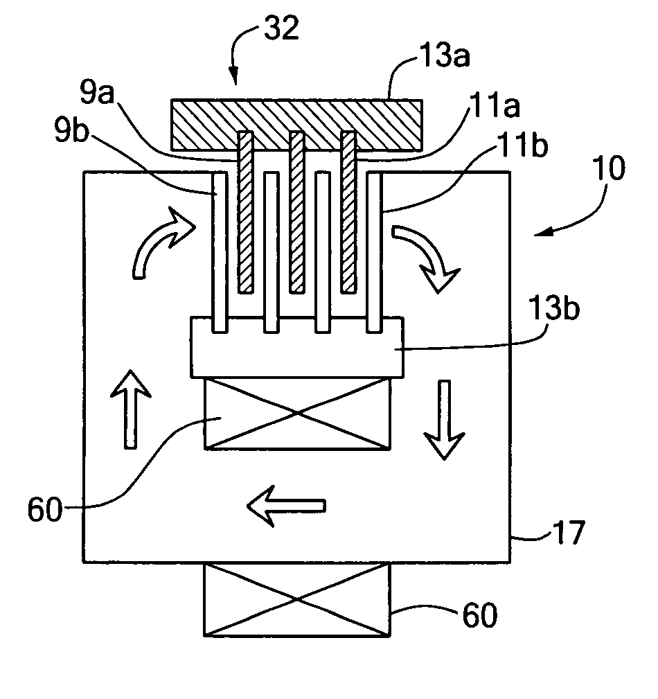
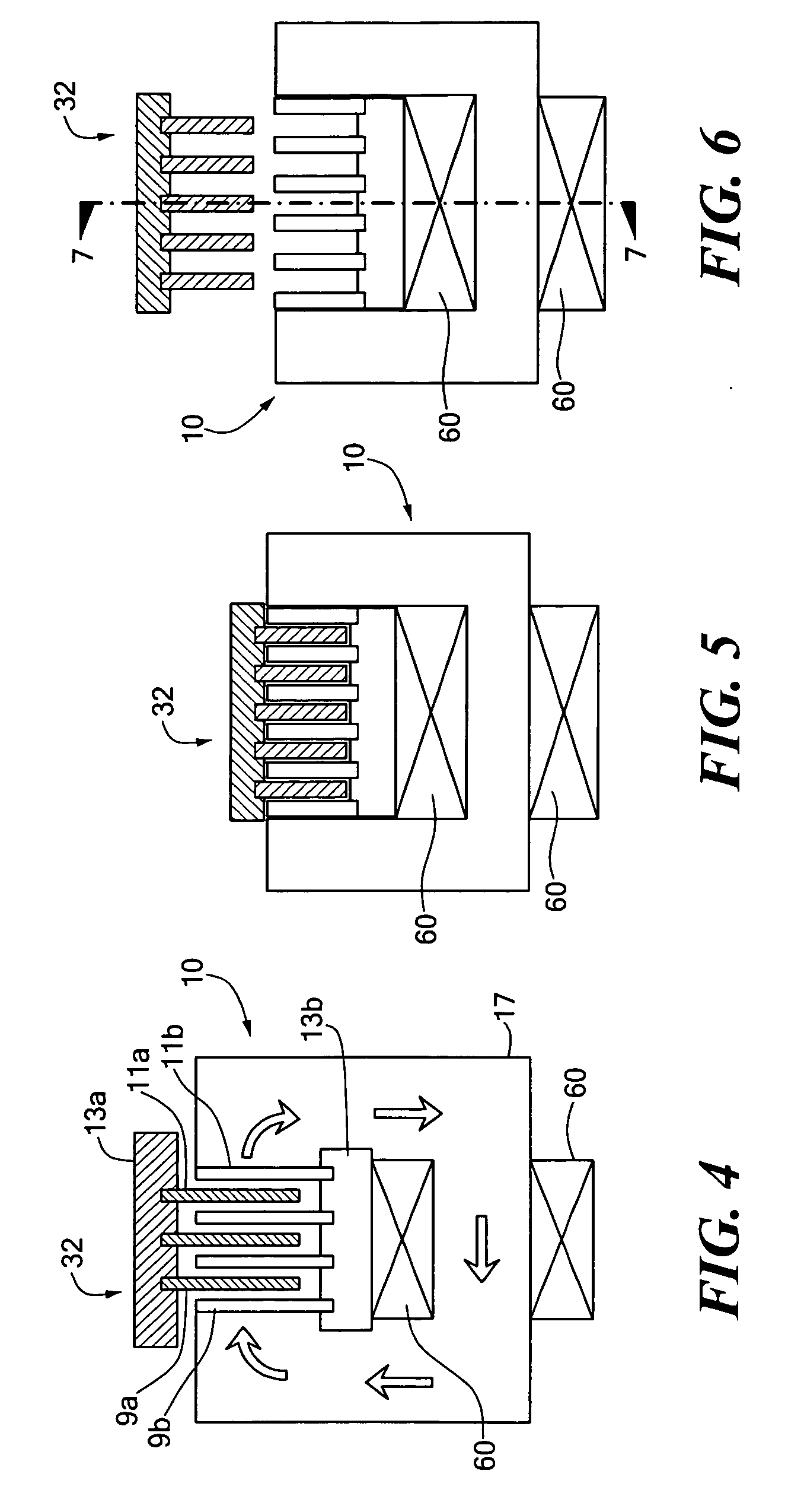
[0011]The invention results from the realization that an improved rotary reluctance motor is effected by orienting the windings of the coils to produce flux through a set of interleaved rotating disks, and by making the disks thin and well-centered, the disks need not be self-supporting but instead support each other, and the disk density can be increased resulting in higher torque per mass and torque per volume. In contrast, the conventional wisdom is that each disk must be sufficiently thick and stiff to support itself and that the gaps between the disks must be large. The invention also results from the realization that with such minimal gap spacing between the disks, there are reduced resistive losses, less coil current is required to generate the necessary flux, and less heat is generated. The invention results from the further realization that increased torque may further be achieved by a large number of interleaved disks including high permeability teeth separated by low permeability material segments, creating a large surface area for electromagnetic shear.
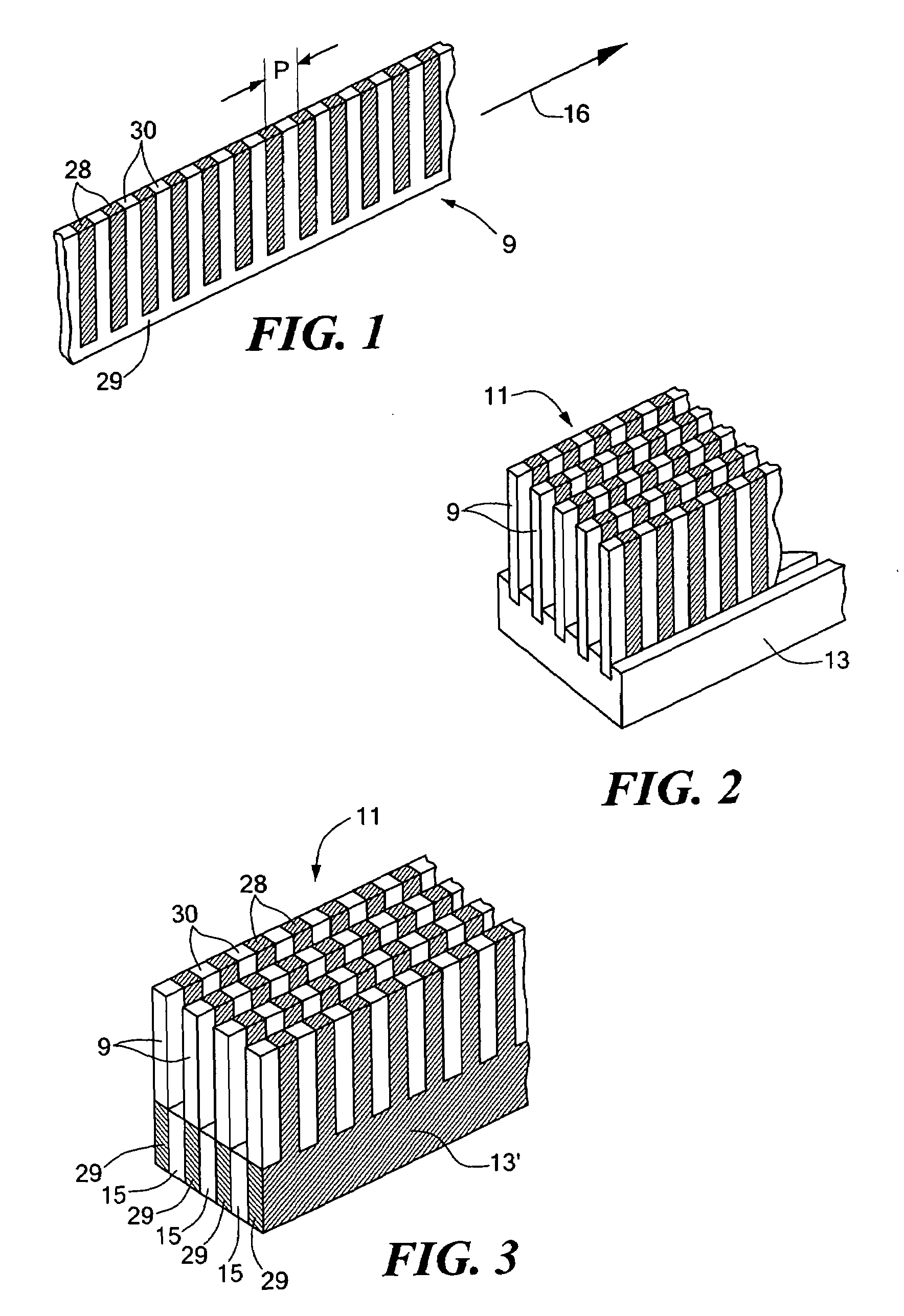
[0013]In one configuration, the set of inner disks are fixed at the inner diameter roots to an inner root assembly, and the set of outer disks are fixed at the outer diameter roots to an outer root assembly, with the root assemblies defining spacing of the disks. The axial clearances between disks may vary, and the disks may touch, but there is an average axial clearance between the disks of the disk stack. Typically, the disks are flexible to tolerate errors in disk flatness and axial misalignment, which allows smaller average axial clearance between the disks. In one variation, there is a gap between the endmost disk of a disk stack and the adjacent flux return and / or a gap between the endmost disk and the adjacent disk, wherein the gap is substantially larger than the average axial clearance between disks of the disk stack. The gap may be tapered to allow for axial misalignment of the inner and outer root assemblies and to minimize the size of the gap during operation of the motor.
[0015]Root assemblies can be fabricated using spacers between disks roots and / or a collar. The root assemblies are preferably made of low permeability materials, and discontinuities can be used to avoid circumferential eddy currents. A root assembly may further include multiple discontinuities which are staggered to provide greater mechanical strength.

Problems solved by technology

Conventional electric motors, both rotary and linear, have very poor torque and force density.
These mechanical methods generally involve noise, wear, backlash, poor shock tolerance, and high reflected inertia.
The fluidic methods tend to increase system complexity due to the addition of a fluid system.
Fluid systems are also harder to control than electric systems.
Due to seal wear, the fluid methods are unreliable and can contaminate sensitive environments when the working fluid leaks.
Such a design, however, results in a fairly low force density.
The motor therein described uses interleaved disks and radial teeth to provide higher torque than conventional motors, however, the torque is still sharply limited due to the use of thick, self-supporting disks and large gaps between disks.

Method used


Image

  • Rotary reluctance motor
  • Rotary reluctance motor
  • Rotary reluctance motor

Examples


Embodiment Construction

[0103]Aside from the preferred embodiment or embodiments disclosed below, this invention is capable of other embodiments and of being practiced or being carried out in various ways. Thus, it is to be understood that the invention is not limited in its application to the details of construction and the arrangements of components set forth in the following description or illustrated in the drawings. If only one embodiment is described herein, the claims hereof are not to be limited to that embodiment. Moreover, the claims hereof are not to be read restrictively unless there is clear and convincing evidence manifesting a certain exclusion, restriction, or disclaimer.

[0104]FIG. 1 depicts a single blade 9 including a plurality of alternating high permeability teeth 28 and low permeability teeth 30 extending from blade root 29 and defining pitch P. In FIG. 1, teeth 28 and 30 extend perpendicular to the longitudinal axis of the blade but this is not a necessary limitation of the subject in...


PUM


Abstract

A rotary reluctance motor includes a set of inner disks each having an inner diameter root, an outer diameter free end, and a plurality of alternating high permeability teeth and low permeability material segments. A set of outer disks is interleaved with the inner disks to form a disk stack. Each outer disk has an outer diameter root, an inner diameter free end, and a plurality of alternating high permeability teeth and low permeability material segments. The inner and outer disks are configured to bear against and support each other in response to axial magnetic forces. Flux return portions are disposed axially adjacent the disks at each end of the disk stack. A coil is associated with the roots of one of the sets of disks and configured to provide axial flux through the disk stack to rotate one set of disks with respect to the other set of disks.

Description

RELATED APPLICATIONS[0001]This application is a continuation-in-part of U.S. patent application Ser. No. 11 / 732,044 filed Apr. 2, 2007, which is a continuation of prior U.S. patent application Ser. No. 10 / 726,420 filed Dec. 3, 2003, which claims the benefit of and priority to U.S. provisional application Ser. No. 60 / 431,604 filed Dec. 6, 2002, each of which are incorporated herein by reference.FIELD OF THE INVENTION[0002]This subject invention relates to reluctance motors, and in particular rotary reluctance motors.BACKGROUND OF THE INVENTION[0003]Conventional electric motors, both rotary and linear, have very poor torque and force density. For heavy lifting applications, mechanical means such as gears and screws are more typically used. Fluidic devices including pneumatic and hydraulic systems are also used. These mechanical methods generally involve noise, wear, backlash, poor shock tolerance, and high reflected inertia. The fluidic methods tend to increase system complexity due t...

Claims


Application Information

Patent Timeline
IPC IPC(8): H02K37/08H02K5/167H02K1/06
CPCH02K19/103H02K41/03H02K37/08
Inventor POTTER, STEVEN D.
Owner FOSTER-MILLER
Why Eureka
Eureka Blog
Learn More