Piezoelectric sensor device, and polarization method of piezoelectric body of piezoelectric sensor device
- Summary
- Abstract
- Description
- Claims
- Application Information
AI Technical Summary
Benefits of technology
Problems solved by technology
Method used
Image
Examples
first embodiment
[0038]Following, we will describe a first embodiment of the present invention while referring to the drawings.
Schematic Configuration of Ultrasonic Sensor
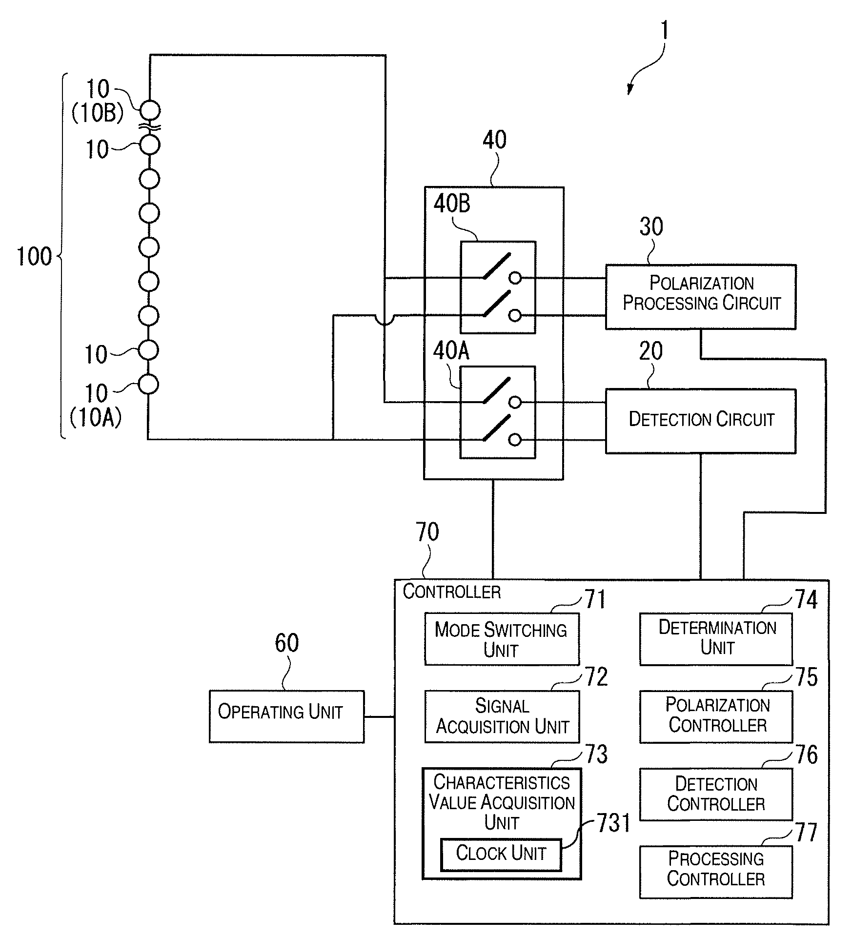
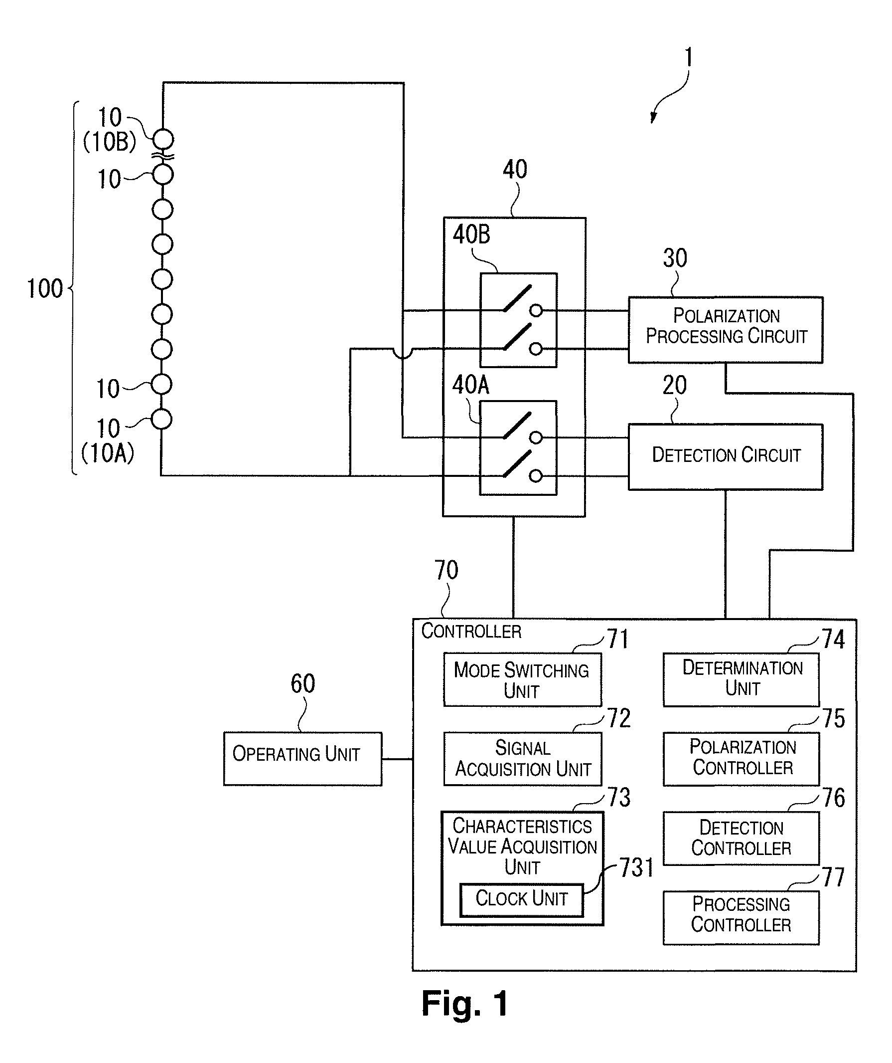
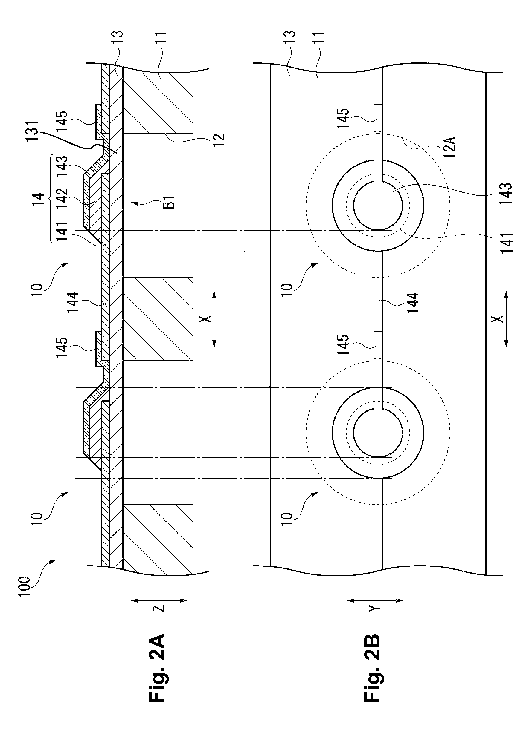
[0039]FIG. 1 is a diagram showing the configuration of an ultrasonic sensor 1 as the piezoelectric sensor device. This ultrasonic sensor 1 is a sensor for detecting the distance between the ultrasonic sensor 1 and the object to be detected as well as the state of the object to be detected by receiving ultrasonic waves reflected by the object to be detected that were sent to the object to be detected. This kind of ultrasonic sensor 1 can be used for various kinds of devices that send or receive ultrasonic waves, such as a biopsy device for measuring in vivo blood vessel position, blood flow speed, blood pressure and the like, for example, by sending and receiving ultrasonic waves, a stress measuring device for measuring pressing force or sheer force acting on an elastic film by detecting through use of ultrasonic waves the movement ...
second embodiment
[0107]Following, we will describe a second embodiment of the present invention while referring to the drawings.
[0108]With the previously described first embodiment, whether or not the piezoelectric film 142 polarization properties are in a stable state or not was determined by measuring the elapsed time after polarization processing of the piezoelectric film 142, but with this embodiment, the difference from the first embodiment is that this is further determined by using receiving signals. Note that with the description below, the same or roughly the same parts that have already been described are given the same code number, and an explanation of those will be omitted.
[0109]FIG. 6 is a schematic diagram showing the constitution of the ultrasonic sensor 1A of this embodiment.
[0110]As shown in FIG. 6, the ultrasonic sensor 1A of this embodiment is equipped with a receiving element group 100, a detection circuit 20, a polarization processing circuit 30, a connection switching circuit ...
modification examples
[0140]Note that the present invention is not restricted to the embodiments described above, and the present invention includes variations and improvements within a scope that can achieve the objects of the present invention.
[0141]With the second embodiment noted above, a determination of whether or not this is in an unstable state was made when the elapsed time (t) was greater than the second time t2 using the signal differential value, but the invention is not limited thereto. For example, it is also possible to determine whether in a stability transition state, or whether in an unstable state with t≦t2 as well using the signal differential value. In specific terms, during the period when the elapsed time (t) is 0≦t≦t1, when the signal differential value exceeds the stability upper limit value, this is determined to be in a stability transition state, and if the signal differential value is within the threshold range from the stability upper limit value to the stability lower limit...
PUM
| Property | Measurement | Unit |
|---|---|---|
| Time | aaaaa | aaaaa |
Abstract
Description
Claims
Application Information
 - R&D
- Intellectual Property
- Life Sciences
- Materials
- Tech Scout
- Unparalleled Data Quality
- Higher Quality Content
- 60% Fewer Hallucinations
Browse by: Latest US Patents, China's latest patents, Technical Efficacy Thesaurus, Application Domain, Technology Topic, Popular Technical Reports.
© 2025 PatSnap. All rights reserved.Legal|Privacy policy|Modern Slavery Act Transparency Statement|Sitemap|About US| Contact US: help@patsnap.com


