Multiple Thermal Cutting Device and Multiple Thermal Cutting Method

Active Publication Date: 2007-10-18
KOMATSU IND CORP
View PDF3 Cites 34 Cited by
  • Summary
  • Abstract
  • Description
  • Claims
  • Application Information

AI Technical Summary

Benefits of technology

[0032] According to another aspect of the present invention, a hybrid thermal cutting apparatus which includes both a laser head and a plasma torch, also includes: a table for supporting a plate material; a shift mechanism for shifting each of said laser head and said plasma torch over said table; a distance detector which detects the distance between said laser head and said plate material; and a controller which controls the operation of said plasma torch and said laser head. And the controller calculates distance data between said plate material and said plasma torch based upon distance data which has been measured by said distance detector during laser processing, and performs plasma processing upon said plate material based upon this distance data which has been calculated. By doing this, and by compensating the distance data which has been measured during the laser processing, it is possible to take advantage of this distance data also during the plasma processing, so that it is possible to omit any measurement of distance when performing the plasma processing.
[0033] According to yet another aspect of the present invention, a hybrid thermal cutting apparatus which includes both a laser head and a plasma torch, also includes: a table for supportin

Problems solved by technology

Generally, with a thermal cutting apparatus, reduction of the running cost (for example, the cost of electrical power consumption for generating a laser beam, or the cost due to ablation or the like of the electrode of a plasma torch) is an extremely important problem.
However, no particular technique is disclosed in the above described patent documents for reducing the running cost.
Furthermore although, when thermal cutting heads of two types, laser and plasma, are mounted, it is considered that the heads exert a mutual influence

Method used


Image

  • Multiple Thermal Cutting Device and Multiple Thermal Cutting Method
  • Multiple Thermal Cutting Device and Multiple Thermal Cutting Method
  • Multiple Thermal Cutting Device and Multiple Thermal Cutting Method

Examples


Example

Embodiment 1

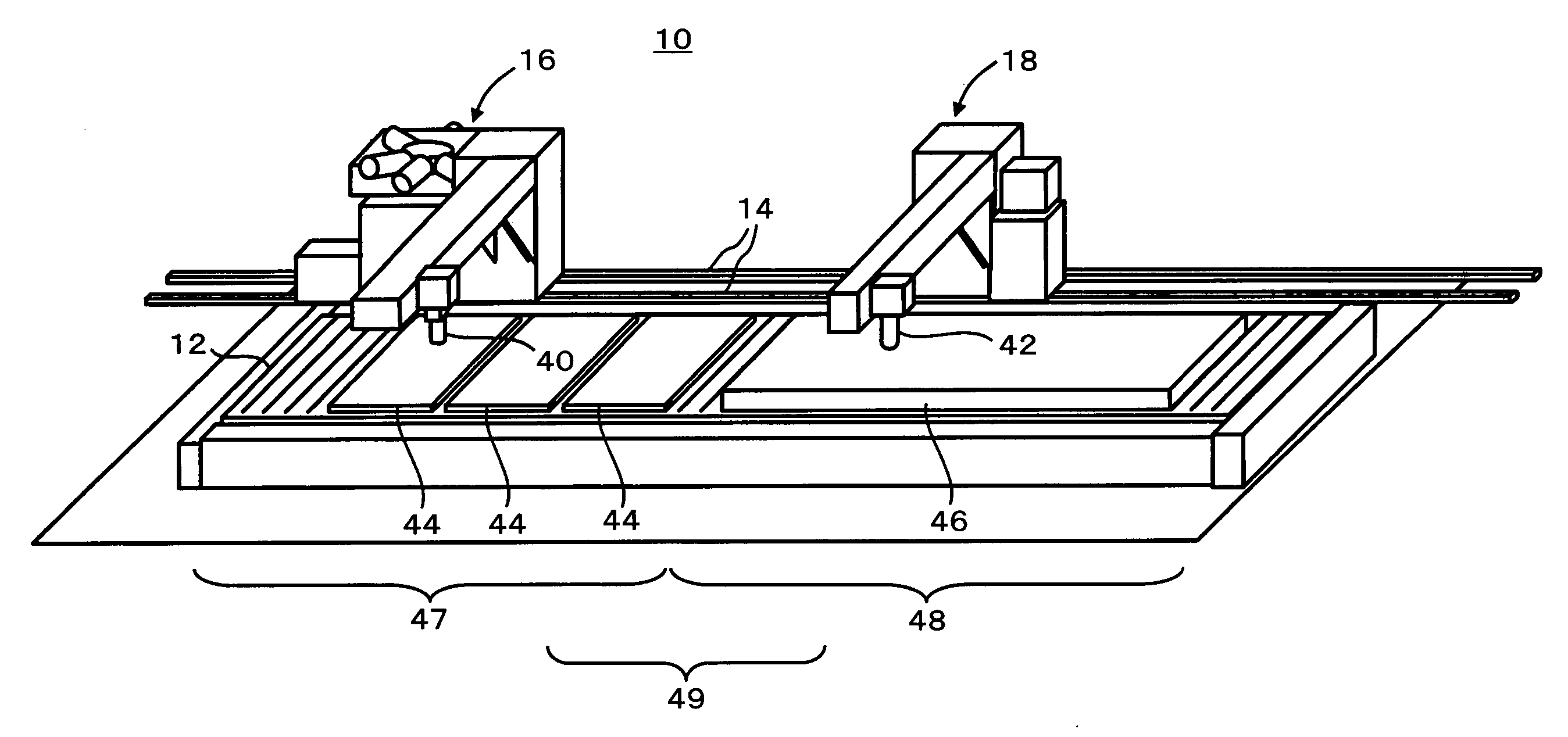
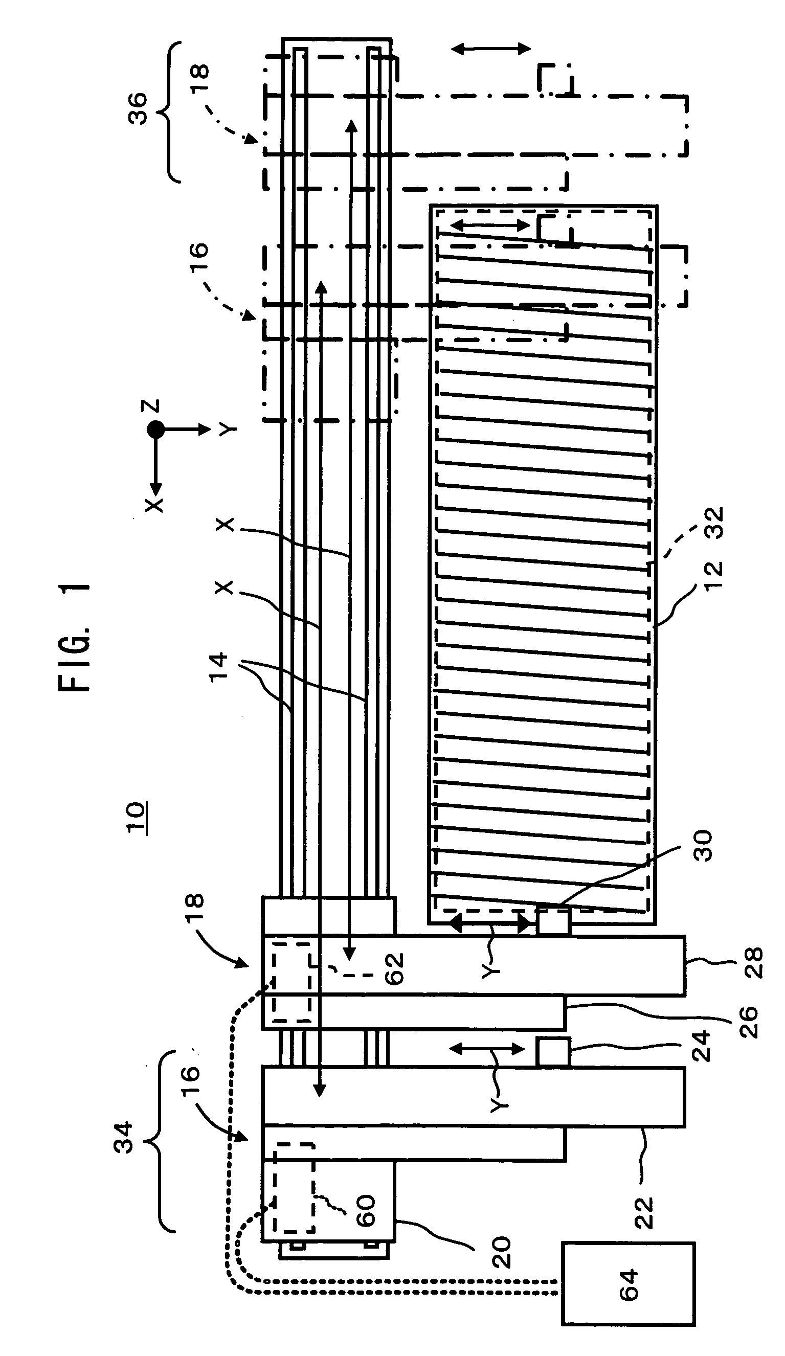
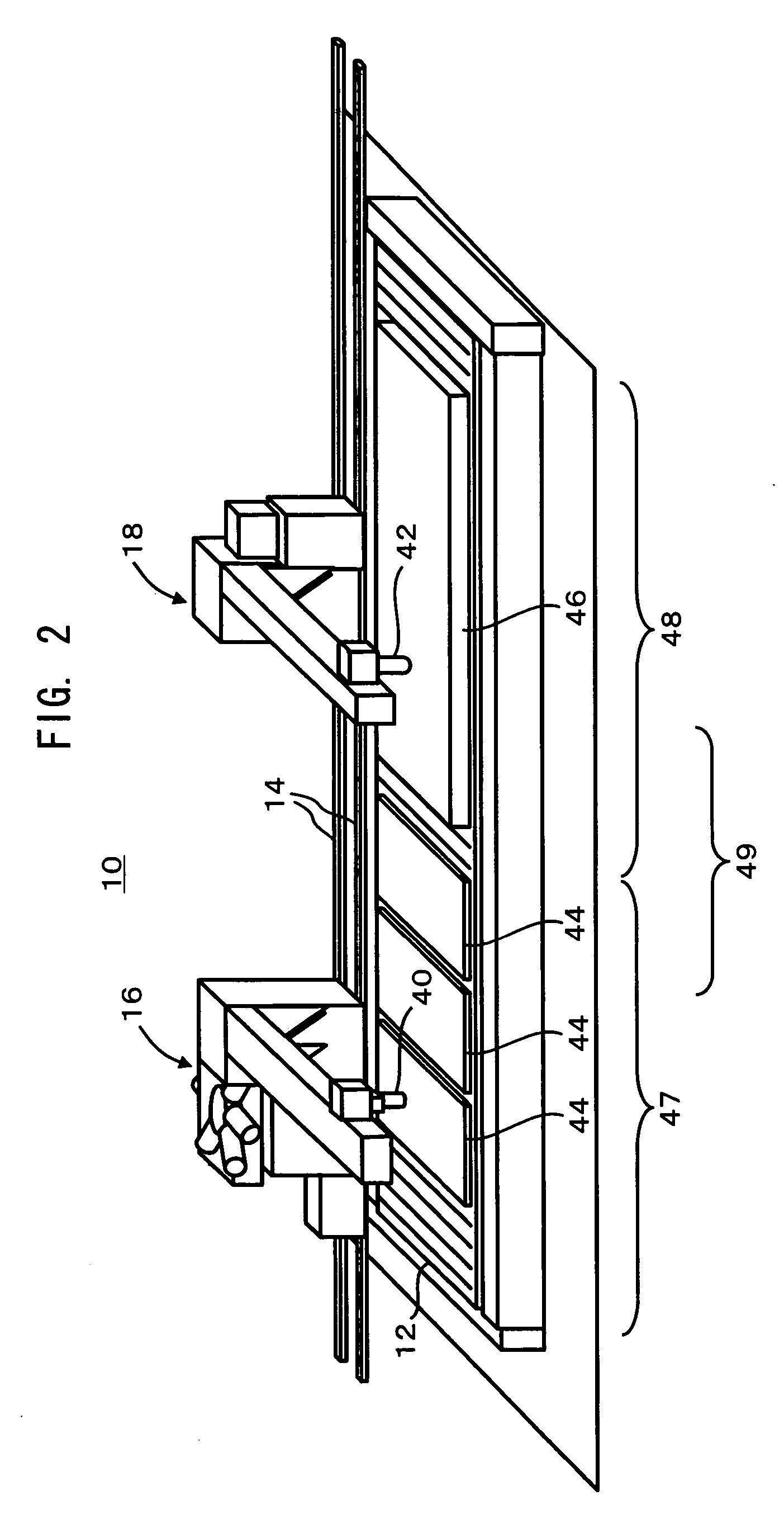
[0059]FIG. 1 is a plan view showing the overall structure of a hybrid thermal cutting apparatus according to one embodiment of the present invention. And FIGS. 2 through 5 are perspective views of this hybrid thermal cutting apparatus, in various operational states.

[0060] As shown in FIGS. 1 through 5, this hybrid cutting apparatus 10 comprises a box shaped table 12 which is set up upon a floor. The rectangular upper surface of this table 12 is made in the form of slats, i.e. a lattice, and upon this there is mounted a plate material 44, 46, 50, or 56, which is the material to be cut. An orthogonal X-Y-Z coordinate system is defined for use during numerical calculation processing for controlling the cutting position of this plate material upon the table 12. The X axis of this orthogonal X-Y-Z coordinate system is parallel to the long side of the upper surface of the table (the horizontal direction in FIG. 1); the Y axis is parallel to the short side of the upper surfac...

Example

[0101] Next, a second embodiment of the present invention will be explained with reference to FIGS. 10 through 24. In this embodiment, as described hereinafter, the thermal cutting heads are supported by a so called cantilever method, in which the laser head and the plasma torch are both shiftably installed upon the same side surface of a frame which is shaped approximately as a letter “C”. Since, for this embodiment, the explanation of the first embodiment may be invoked as appropriate, accordingly, in the following explanation, the description will principally focus upon the points of difference.

[0102]FIG. 10 is an explanatory figure showing a summary of the structure of the hybrid thermal cutting apparatus 10A according to this embodiment. And FIG. 11 is a perspective view of this hybrid thermal cutting apparatus 10A. The hybrid thermal cutting apparatus 10A of this embodiment may, for example, comprise a processing apparatus main body (200, 300, 500, 600, etc.) and a control de...

Example

[0129] Next, a third embodiment of the present invention will be explained based upon FIGS. 16 and 17. In this embodiment, the amount of electrical power consumption during the laser process is reduced. FIG. 16 is a flow chart showing a summary of the processing for creating the laser processing program. When the processing program generation device 80 receives each of manufactured product shape data 82 (S21), plate material data 84 (S22), and process accuracy data (S23), it performs arrangement (nesting) of the manufactured products (S24), and creates cutting line data (S25).

[0130] The processing program generation device 80 classifies the cutting line data into either data for lines for laser processing or data for lines for plasma processing, just as described above with reference to the first embodiment (S26). In the case of cutting line data suitable for laser processing, the processing program generation device 80 creates a laser processing program (S28). And, in the case of ...


PUM

PropertyMeasurementUnit
Lengthaaaaaaaaaa
Thicknessaaaaaaaaaa
Distanceaaaaaaaaaa

Abstract

A hybrid thermal cutting apparatus has both a laser head and a plasma torch, both of which can be controlled independently, can perform both laser processing and plasma processing, thus reducing the running costs. A large number of cutting lines for cutting out various types of manufactured products from plate materials are classified into a laser cutting type and a plasma cutting type, according to the cutting length, whether they are the external periphery of manufactured products or apertures, the size of the manufactured products or the apertures, the required process accuracy, the plate thickness, or the like. The lines of the laser cutting type are cut by laser processing, while the lines of the plasma cutting type are cut by plasma processing.

Description

TECHNICAL FIELD [0001] The present invention relates to a hybrid thermal cutting apparatus which has thermal cutting heads of two types, laser and plasma, and to a hybrid thermal cutting method. BACKGROUND OF THE INVENTION [0002] In U.S. Pat. No. 5,350,897, there is disclosed an apparatus in which two thermal cutting heads, plasma and laser, are installed in line to a turret punch press. Either the plasma cutting head or the laser cutting head can be chosen and brought to a cutting position. [0003] In Japanese Laid Open Patent Publication Heisei 9-108875, there is disclosed an apparatus in which, to a single gantry which can traverse a table and shift in the vertical direction, there are mounted one or two carriages which are shiftable in the horizontal direction, and two thermal cutting heads, plasma and laser, are installed in line to each of these carriages. On each carriage, either one of the plasma cutting head and the laser cutting head may be selected and used. If two carriag...

Claims


Application Information

Patent Timeline
IPC IPC(8): B23K26/08B23K10/00B23K26/00B23K26/042B23K26/064B23K26/082B23K26/38
CPCB23K10/006B23K26/0093B23K26/0876B23K26/38B23P23/00B23K37/0229B23K37/0235B23K2201/18B23K28/02B23K2101/18
Inventor YAMAGUCHI, YOSHIHIROKABATA, TETSUYAKAMADA, IKUO
Owner KOMATSU IND CORP
Why Eureka
Try Eureka