
Strainer dispenser and method of use

a strainer and dispenser technology, applied in the direction of rigid containers, pile separation, transportation and packaging, etc., can solve the problems of clogging the spray gun, dust can fall into the paint cup, and the uniformity of the painting is compromised, so as to minimize the “open” time of the filter mesh, avoid contamination, and easy to remove

Active Publication Date: 2015-08-25
LOUIS M GERSON CO INC
View PDF12 Cites 0 Cited by
  • Summary
  • Abstract
  • Description
  • Claims
  • Application Information

AI Technical Summary

Benefits of technology

[0010]In some aspects, a method is provided of loading a stack of conical paint strainers within a dispenser while minimizing strainer contamination. The method includes the following steps: Providing the stack of strainers that is enclosed within a protective material. Placing the enclosed stack of strainers in the dispenser. Removing the protective material from the stack of strainers while the stack of strainers is in the dispenser.
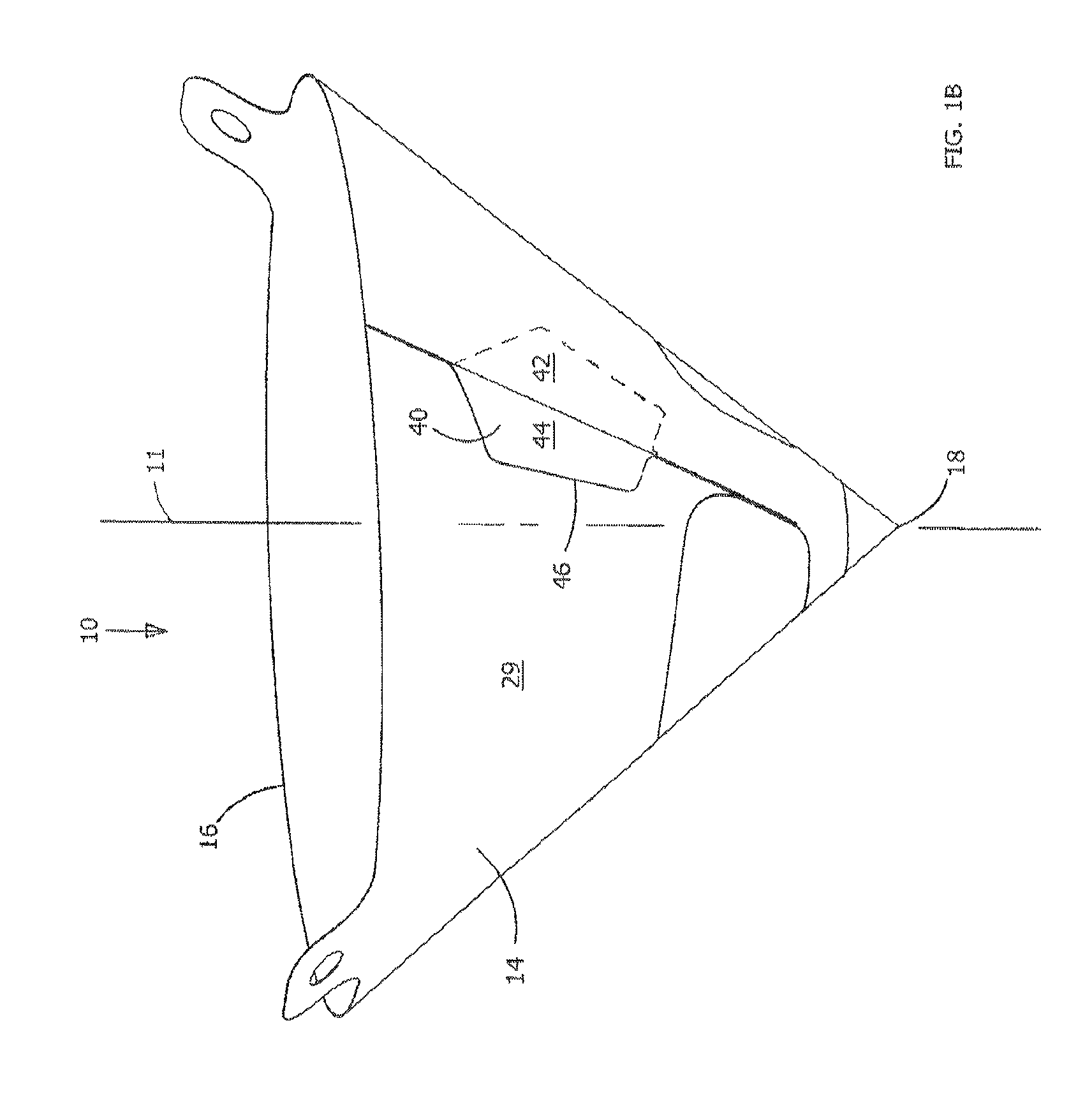
[0016]The above aspects provide a strainer having a dispensing tab, located on the outer surface of the strainer, which provides a manual grip area that allows the strainer to be withdrawn from its packaging or from a dispenser while avoiding direct contact with the strainer body or filter. Furthermore, the subject invention can be provided at no additional cost of material or labor during the manufacturing of the strainer.
[0017]If the strainer is packed in the traditional poly bag or poly tubing, the dispensing tab of the strainer can be can be conveniently grasped by the painter for removal from the stack within the bag. Furthermore, the removal will be from the tip end, which provides for easier removal than if the strainer is de-nested from the rim at its open end, in which case the rim or tabs on the strainer can catch in the soft plastic bag or film and interfere with removal.
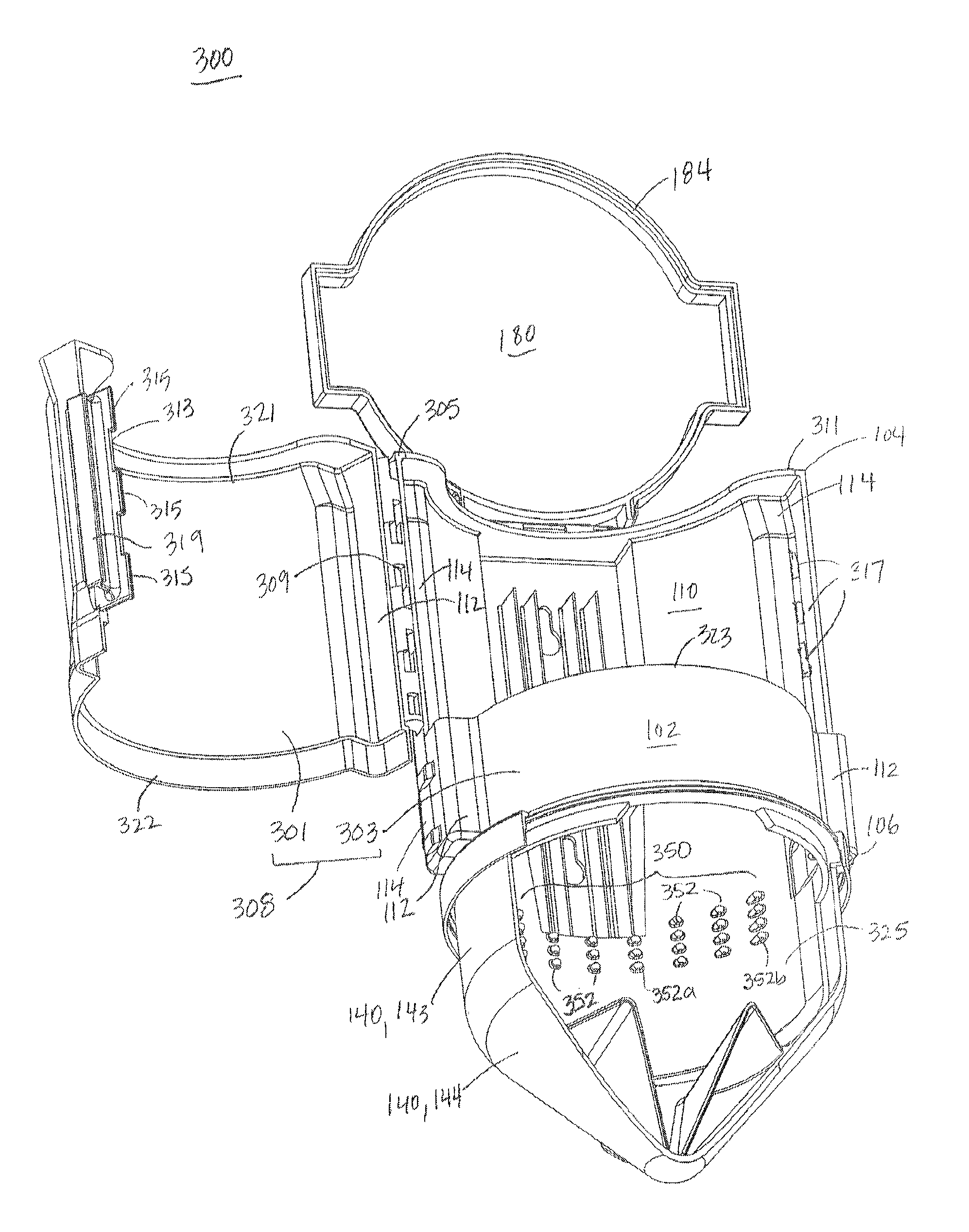
[0018]The above aspects also include a dispensing unit which can be loaded with multiple stacked strainers, and allows the dispensing tab to be gripped for dispensing of the strainer from the bottom of the dispenser without direct contact with the filter portion of the strainer. The bottom-dispensing feature is more convenient than some conventional top-dispensers, can include a closable lower end that provides complete protection of the strainer during storage, and enables the strainer to be removed without direct contact of the tip and filter area.
[0019]A stack of strainers is wrapped in a protective material, creating a pod. The wrapping material is perforated in such a manner that enables the wrapping to be opened and removed from the stack of strainers once the stack is placed within the dispenser. For example, both the top and the bottom of the pod are sealed in order to provide dust-free storage and the protective material extends beyond the apex of the stack of strainers to provide a gripping area that may be used to remove part of the protective wrapping. By doing so, the pod of wrapped strainers can be placed within the dispenser without exposure of the strainer itself or the filter mesh to ambient particulates in the air and without the risk of contamination from body oils or substances on the hand of the painter. Ideally, the strainers have been manufactured by automated means to avoid touching of the filter mesh during production and the stack of strainers is packaged by automated means to avoid handling of the completed strainer and touching of the filter mesh. Automated production also minimizes the “open” time of the filter mesh in ambient air, reducing the time of exposure to particulates in the environment and lends itself to in-line cleaning and de-contamination of the strainer from any particulates that may have accumulated on the strainer mesh or blank during manufacturing. Nevertheless, the use of the protective wrapping to allow contamination-free placement within the dispenser is, in itself, of significant benefit.

Problems solved by technology

If a spray gun clogs during use, the uniformity of the painting is compromised.
Dust can dislodge from the filter mesh, drop into the paint cup and can appear as blemishes on the surface of a car or can clog the spray gun.
Touching of the filter can transfer body oils or contaminants on the hand to the filter and can result in spotting or “fish eyes” in the paint job, necessitating repainting.
Although satisfactory for transportation of the product, this type of packaging is less than desirable for the paint shop.
However, even if the strainers are left in the bag, the bag may end up on a shelf or a workbench or even on the floor, where it can be damaged, knocked around or left open.
A damaged or open package allows dust to enter the bag, and thus is not desirable.
If the strainer is dispensed from the bag tip first, the painter is likely to touch and contaminate the outside of the filter.
Some conventional dispensers are merely tubes that hold a stack of strainers, and the open ends of the tube do little to avoid exposure of the tip and filter area of the strainer to manual contamination or contamination from dust in the air.
If the dispenser is mounted at or near chest level, it is difficult to reach into the top of the dispenser, especially when the stack of strainers is almost used and the painter has to reach far down the tube or box to remove the strainer.
However, this slot leaves the carton open to contamination by dust and particles in the atmosphere.
Some conventional dispensers are configured to have the strainers dispense from the bottom of the tube, but this has two drawbacks.
First, having the strainers dispense from the dispenser bottom leaves the tip and filter of the strainer exposed to the atmosphere, allowing contamination from dust and particulates.
Secondly, in order to dispense a strainer from the stack, the strainer is gripped by the tip or filter area of the strainer.
This can physically damage the filter or weaken its bond to the paper and / or exposes the filter to contamination from body oils or other chemicals on the hands and fingers.
Furthermore, the removal will be from the tip end, which provides for easier removal than if the strainer is de-nested from the rim at its open end, in which case the rim or tabs on the strainer can catch in the soft plastic bag or film and interfere with removal.

Method used


Image

  • Strainer dispenser and method of use
  • Strainer dispenser and method of use
  • Strainer dispenser and method of use

Examples


Embodiment Construction

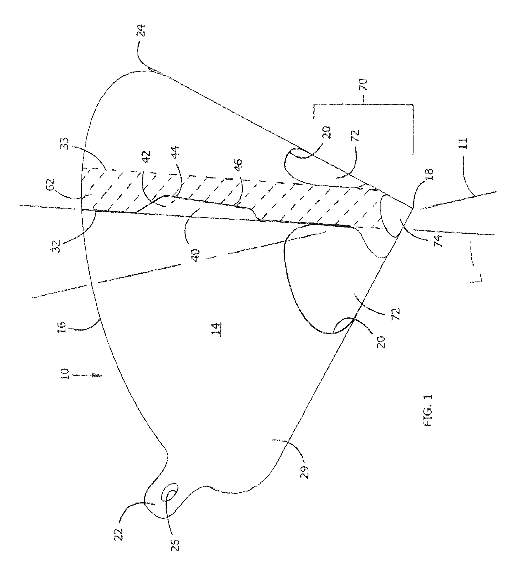
[0046]Referring now to FIG. 1, a disposable liquid strainer 10 is shown which includes a hollow, conical body 14 having an open, generally circular end defined by a rim 16. The conical body tapers to an apex 18 that is opposed to the rim 16. The rim may include rim tabs 22, 24 that permit positioning and support of the strainer 10 or allow removal of the strainer from a spray gun cup by an area free of paint. The rim tabs 22, 24 extend outward from the rim 16 so as to extend the exterior surface 28 of the conical body 14. The rim tabs 22, 24 serve as handles by which the strainer 10 can be held and positioned, and each includes a through hole 26 by which the strainer can be secured to a stand if desired. The strainer 10 is provided with a filtering region 70 in the vicinity of the apex 18 that includes side filter areas 72 and an apex filter area 74.

[0047]In addition, the strainer 10 is provided with a dispensing tab 40 which protrudes from an exterior surface 29 of the strainer 10 ...


PUM

PropertyMeasurementUnit
pore sizeaaaaaaaaaa
diameteraaaaaaaaaa
arc angleaaaaaaaaaa

Abstract

A method of loading stacked strainers in a dispenser while minimizing strainer contamination is disclosed. The method includes providing a stack of strainers that is enclosed in a protective material to form a pod, placing the pod within a dispenser, and removing the protective material from the pod of strainers while the strainers are in the dispenser. The strainers dispensed from the thus loaded dispenser avoid being contamination during loading. The protective material may be perforated to facilitate removal from the stack, and include an extended portion to be grasped during removal from the dispenser.

Description

CROSS-REFERENCE TO RELATED APPLICATIONS[0001]This application is the National Stage of International Application No. PCT / US2010 / 038834, filed Jun. 16, 2010, which claims benefit of International Application No. PCT / US2009 / 054103, filed Aug. 18, 2009. The content of these applications is hereby incorporated by reference in its entirety.BACKGROUND OF THE INVENTION[0002]1. Field of the Invention[0003]The invention relates to a liquid strainer, more particularly to a paint strainer, to a method of loading a dispenser with paint strainers, and to a device for storing and dispensing same.[0004]2. Background of the Invention[0005]Disposable paint strainers are used to filter paint that is to be sprayed from a spray gun, and consist of an impervious structure, usually a low-cost paper board body, with a filter insert. The strainer is usually produced in a conical shape, but this shape is not necessarily required. The conical strainer is typically placed in the opening of a spray gun cup and...

Claims


Application Information

Patent Timeline
Patent Type & Authority Patents(United States)
IPC IPC(8): B65H1/00B65D75/58A47J31/08A47F1/08B65D85/62
CPCA47F1/085A47J31/08B65D75/5833B65D85/62B65D2203/02
Inventor GERSON, RONALD L.BRUNELL, ROBERT A.LAPOINTE, PIERREMCCOMBE, MICHAEL H.
Owner LOUIS M GERSON CO INC
Learn More