Side shield structure for vehicle seat

a technology for vehicle seats and side shields, applied in the direction of chairs, furniture parts, pedestrian/occupant safety arrangements, etc., can solve the problems of reducing the strength of side shields, and achieve the effect of reducing costs

Active Publication Date: 2015-08-25
TOYOTA BOSHOKU KK
View PDF15 Cites 10 Cited by
  • Summary
  • Abstract
  • Description
  • Claims
  • Application Information

AI Technical Summary

Benefits of technology

[0007]The invention relates to a side shield structure for a vehicle seat, that is capable of inhibiting a reduction in strength due to an opening of a side shield member.
[0009]According to this structure, arranging the reinforcing member that has an opening in a portion corresponding to the opening in the side shield member on the inside surface of the side shield member makes it possible to inhibit a reduction in strength of the side shield member while maintaining the ability to insert the end anchor of the seat belt. In other words, even if the opening in the side shield member is made large in order to make it easier to insert the end anchor of the seat belt, a reduction in strength of the side shield member can be inhibited by the reinforcing member while the appearance is prevented from deteriorating by plugging up the opening with the plug member.
[0011]According to this structure, the reinforcing member is able to be integrally arranged on the inside surface of the side shield member by abutting the joining portion of the reinforcing member against the inside surface of the side shield member and joining them together. Also, the side shield member is able to be efficiently reinforced by forming the box-shaped sectional portion by the side shield member, together with the box-shaped sectional component of the reinforcing member.
[0013]According to this structure, impact force in the lateral direction acting on the side shield member is able to be absorbed by the impact absorbing structure of the reinforcing member. Also, the impact absorbing structure is able to be integrally formed at the same time the reinforcing member is formed by molding synthetic resin, which makes it possible to avoid the trouble of manufacturing the impact absorbing structure separately from the reinforcing member and then assembling the two together, and is thus very effective for reducing costs.

Problems solved by technology

However, while making the opening of the side shield member larger does make it easier to insert the end anchor of the seat belt, it may also lead to a reduction in strength of the side shield member.

Method used


Image

  • Side shield structure for vehicle seat
  • Side shield structure for vehicle seat
  • Side shield structure for vehicle seat

Examples


Embodiment Construction

[0023]Modes for carrying out the invention will now be described according to example embodiments.

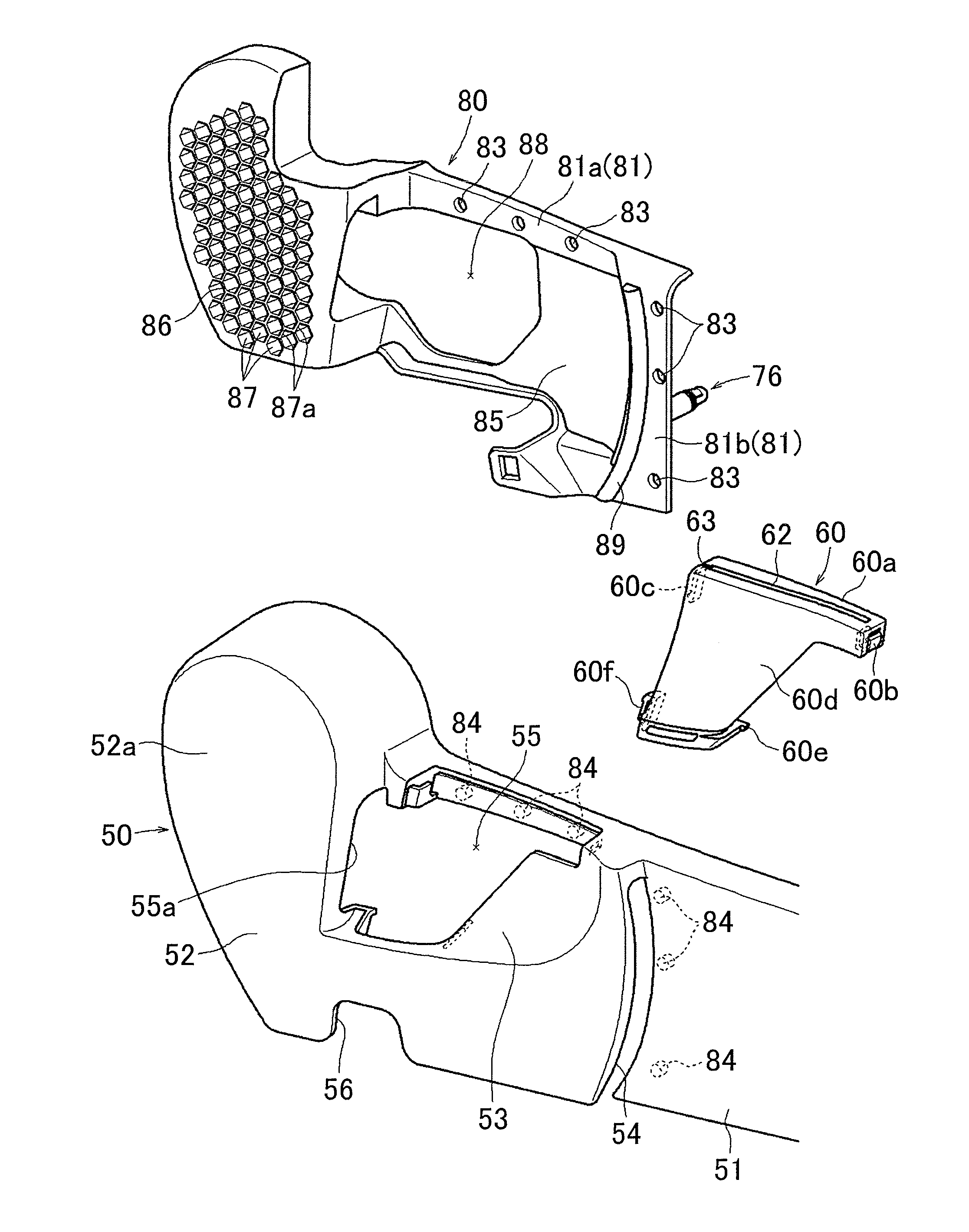
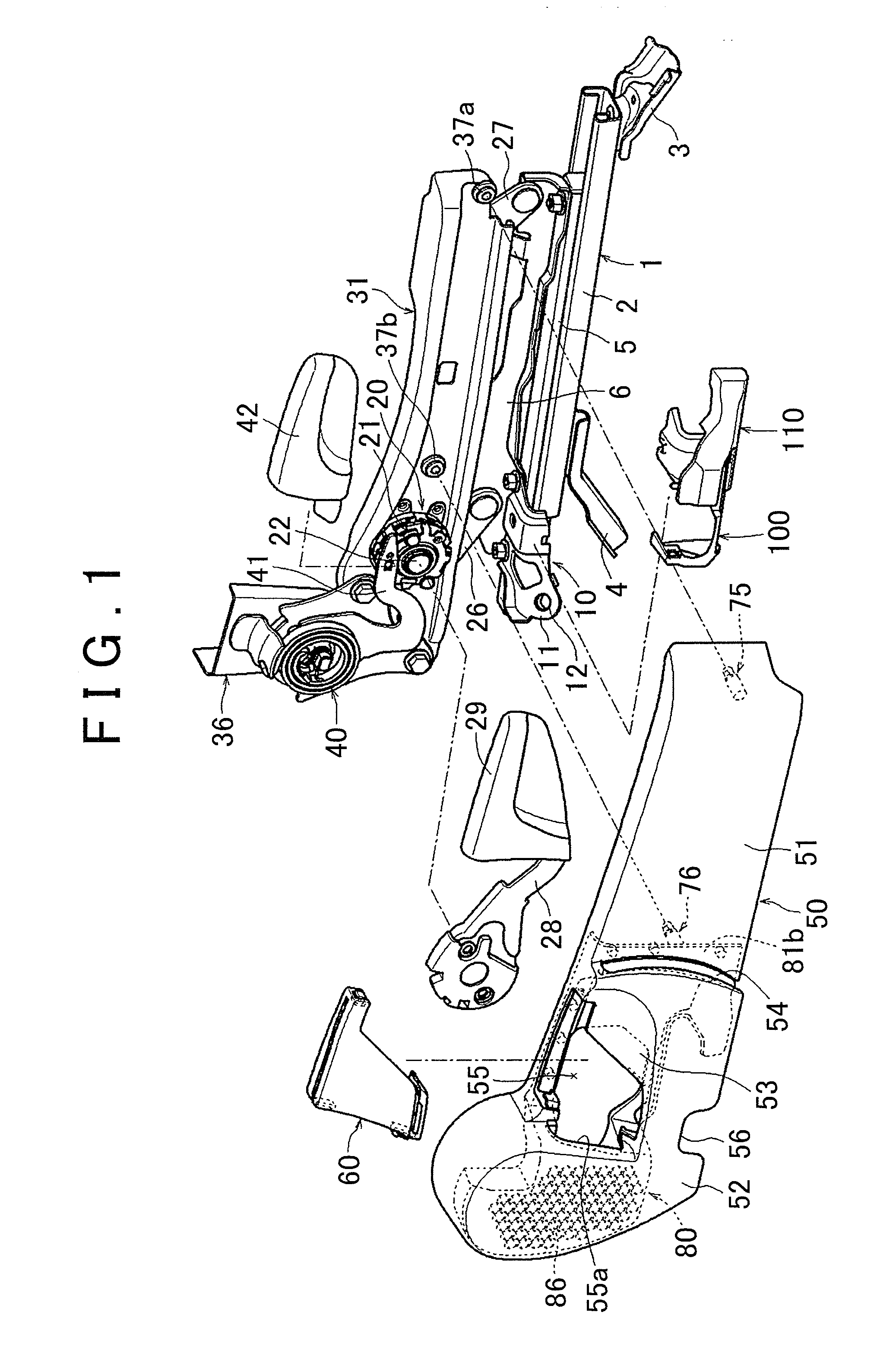
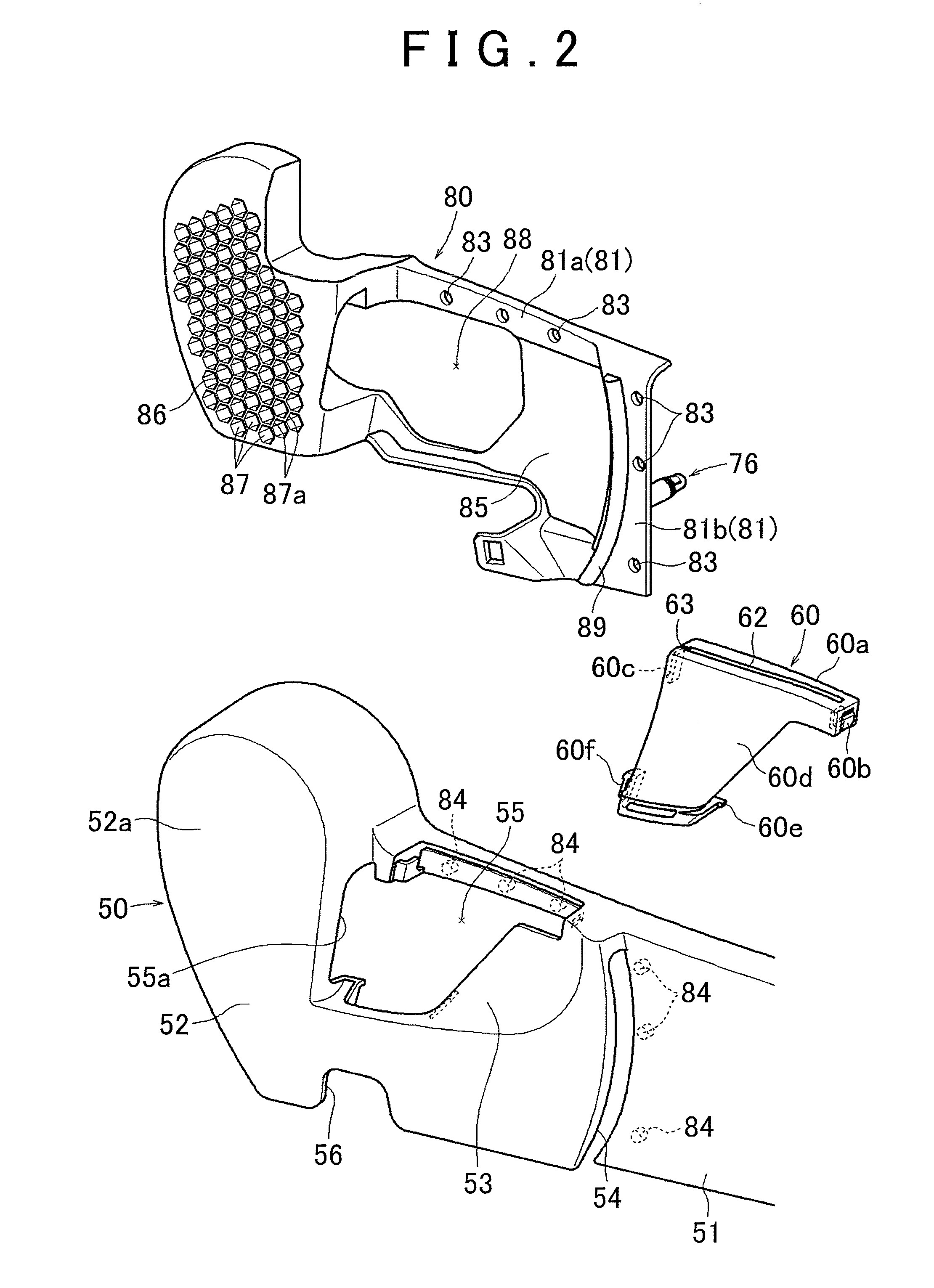
[0024]The side shield structure for a vehicle seat according to an example embodiment of the invention will now be described with reference to the drawings. As shown in FIG. 1, a side frame 31 of a cushion frame that forms a frame portion of a seat cushion of a vehicle seat is attached so as to be able to slide by a slide rail mechanism 1 and raised and lowered by a raising / lowering mechanism 20. The slide rail mechanism 1 includes a lower rail 2 that extends in a longitudinal direction, and an upper rail 5 that is fitted so as to be able to slide along this lower rail 2. The lower rail 2 is fixed to a vehicle cabin floor by a front rail bracket 3 and a rear rail bracket 4. The front rail bracket 3 is fixed to a front portion of the lower surface of the lower rail 2 and the rear rail bracket 4 is fixed to a rear portion of the lower surface of the lower rail 2.

[0025]A bracket 6 is fixed...


PUM


Abstract

A first opening through which an end anchor of a seat belt is inserted from above is formed in a side shield member that covers a side portion of a seat cushion. A plug member that plugs up the first opening and has a belt guide hole through which a belt portion of the seat belt is inserted is fit into the first opening. A reinforcing member having a second opening in a portion corresponding to the first opening is arranged on an inside surface of the side shield member.

Description

INCORPORATION BY REFERENCE[0001]The disclosure of Japanese Patent Application No. 2011-131274 filed on Jun. 13, 2011 including the specification, drawings and abstract is incorporated herein by reference in its entirety.BACKGROUND OF THE INVENTION[0002]1. Field of the Invention[0003]The invention relates to a side shield structure for a vehicle seat.[0004]2. Description of Related Art[0005]One known side shield structure for a vehicle seat has an opening through which an end anchor (that functions as a mounting bracket) of a seat belt can be inserted from above formed in a side shield member (that functions as a cushion finisher) that covers a side portion of a seat cushion (see Japanese Patent Application Publication No. 6-135298 (JP 6-135298 A), for example). A plug member (that functions as a cover body) that plugs up the opening and has a belt guide hole through which a belt portion of the seat belt can be inserted is fit into this opening.[0006]In a side shield structure of a v...

Claims


Application Information

Patent Timeline
Patent Type & Authority Patents(United States)
IPC IPC(8): A47C7/02B60N2/60B60N2/68B60R22/26B60N2/58B60N2/427B60N2/42B60R22/18B60N2/90
CPCB60N2/4235B60N2/42709B60N2/58B60N2/6009B60N2/682B60R22/26B60R2022/1818B60R2022/263
Inventor NAGATA, TOMOAKIKONDO, KOICHIRO
Owner TOYOTA BOSHOKU KK
Why Eureka
Try Eureka