Vehicle door control system and method

a technology for pneumatic doors and control systems, applied in the direction of fluid couplings, rotary clutches, couplings, etc., can solve problems such as system icing risk, and achieve the effect of energy efficient and reliabl

Inactive Publication Date: 2015-08-25
WABCO GMBH
View PDF8 Cites 1 Cited by
  • Summary
  • Abstract
  • Description
  • Claims
  • Application Information

AI Technical Summary

Benefits of technology

[0004]Generally speaking, it is an object of the present invention to provide an improved door control system that is energy efficient and reliable.
[0005]According to an embodiment of the present invention, a device is provided in which a cylinder, by means of a door control valve, can be connected via a first flow path to an air dryer and to a compressor for filling, and can be connected via a second flow path to the air dryer and to atmosphere for emptying. In this case, the air dryer can be operated in drying mode when the cylinder is being filled and operated in regeneration mode when the cylinder is being emptied. In drying mode, the air dryer is exposed to throughflow of air flowing into the cylinder, and in regeneration mode, is exposed to throughflow of air flowing out of the cylinder. As a result, during each operation of the vehicle door, that is, during each cylinder cycle, the ventilated air flows through the air dryer, absorbs moisture there, and discharges this to atmosphere. The air dryer is therefore regenerated during each cylinder cycle, as a result of which maintenance intervals can be reduced to a minimum or completely dispensed with since the air dryer no longer has to be drained manually. Also, there is no risk of icing of the pneumatic system.
[0006]It is favorable that the first flow path and the second flow path are disconnected from each other by means of a cylinder-side check valve and an accumulator-side check valve. As a result, the routing of air in the door control system, especially the flow of air through the first flow path and the second flow path, is correctly carried out.

Problems solved by technology

In the event of failure of the regeneration devices or interruption or incorrect performing of maintenance, there is the risk of icing of the system.

Method used


Image

  • Vehicle door control system and method
  • Vehicle door control system and method

Examples


Embodiment Construction

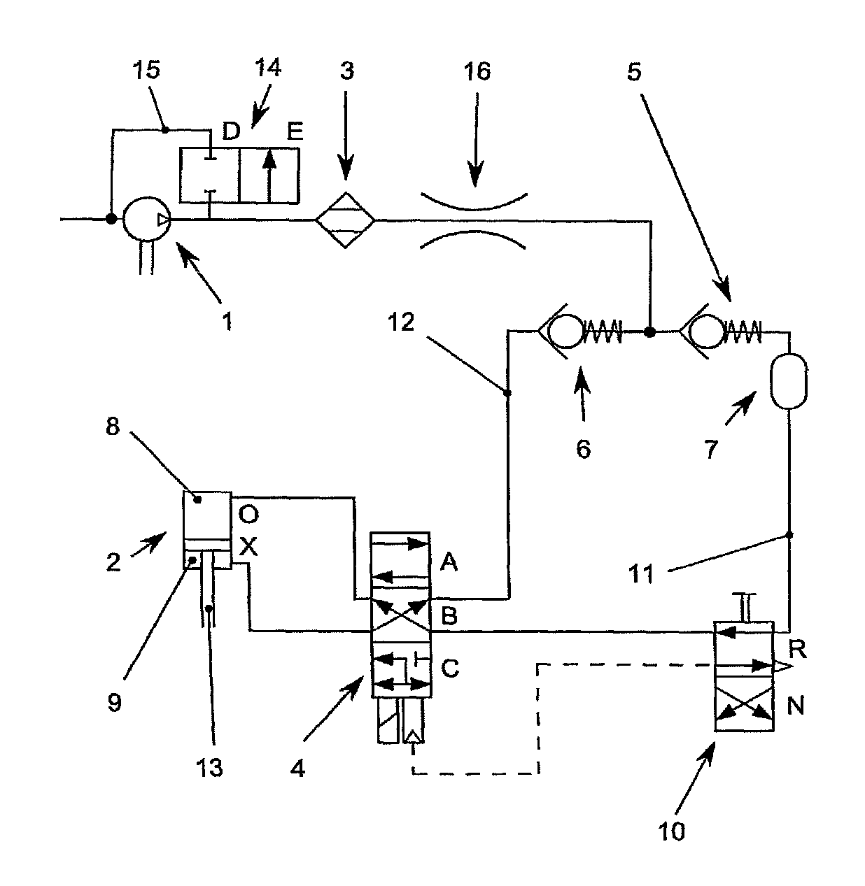
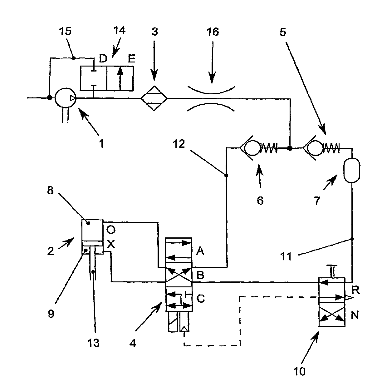
[0019]FIG. 1 is a schematic of a pneumatic door control system with a compressor 1 for producing compressed air, a cylinder 2 for operating a vehicle door, an air dryer 3 and a door control valve 4. The cylinder 2 has a first chamber 8 and a second chamber 9 that are separated from each other by means of a piston 13, which is movably arranged in the cylinder 2. The cylinder piston 13 can systematically occupy a first functional position O and a second functional position X, wherein the cylinder piston 13 occupies the second functional position X as soon as the first cylinder chamber 8 is pressurized. If the second cylinder chamber 9 is pressurized, then the cylinder piston 13 is in the first functional position O.

[0020]A switch between the first functional position O and the second functional position X is achieved by a change of a first switched position A and a second switched position B of the door control valve 4. In FIG. 1, the door control valve 4 is in the second switched pos...


PUM


Abstract

A door control system for a vehicle includes a compressor, an air dryer, a door control valve and at least one cylinder that can be actuated by compressed air. A piston of the cylinder can occupy a first functional position and a second functional position. The air dryer, in drying mode, is exposed to throughflow of the air flowing into the cylinder, and in regeneration mode is exposed to throughflow by the air discharging from the cylinder. The cylinder is pressurized only with compressed air from a compressed air accumulator.

Description

FIELD OF THE INVENTION[0001]The present invention generally relates to a pneumatic door control system and method for vehicles.BACKGROUND OF THE INVENTION[0002]DE 10 2008 011 315 A1 describes a pneumatic vehicle door control system with a double-acting cylinder, which is connected to the vehicle door, the two cylinder chambers of which are connected to the compressor via valves. When the cylinder is being ventilated, the compressed air is relieved into the atmosphere.[0003]As a rule, moisture is extracted from the compressed air, which is produced by a compressor, in an air dryer since dry compressed air has higher quality, which has, inter alia, a positive effect on the service life of the pneumatic system. Such an air dryer must be periodically manually drained and / or regenerated by means of additionally supplied heat. In the event of failure of the regeneration devices or interruption or incorrect performing of maintenance, there is the risk of icing of the system.SUMMARY OF THE ...

Claims


Application Information

Patent Timeline
Patent Type & Authority Patents(United States)
IPC IPC(8): E05F15/50
CPCE05F15/50E05Y2900/531E05Y2900/50
Inventor HELLBUSCH, INGOSTABENOW, UWE
Owner WABCO GMBH
Why Eureka
Try Eureka