Dynamic configuration of body coupled communication devices

a communication device and dynamic configuration technology, applied in the field of bodycoupled communication, can solve the problems of excessive energy consumption, signal level limitations of transmitters, and high energy consumption, and achieve the effect of efficient coupling high frequency signals, high data throughput, and high data efficiency

Inactive Publication Date: 2018-06-26
KONINKLJIJKE PHILIPS NV
View PDF11 Cites 0 Cited by
  • Summary
  • Abstract
  • Description
  • Claims
  • Application Information

AI Technical Summary

Benefits of technology

[0011]The modes of operation of the apparatus can also be divided in depending on a frequency of the generated or processed signals. For example, a high frequency mode may provide a relatively high data throughput while a low frequency mode can be more reliable or energy efficient. When switching from a high frequency mode to a low frequency mode, or vice versa, the number or surface of the couplers can be varied, e.g. to change a coupling surface depending on the frequency. Also a shape or relative arrangement of the couple surfaces can be varied as a function of frequency. For example, smaller plates and comb-like structures are found useful to efficiently couple high frequency signals while larger plates may better couple low frequency signals.

Problems solved by technology

Current BCC devices use couplers that for some applications offer a good performance while for other applications can lead to an excessive use of energy, either to transmit higher signal levels, or to detect very low signal levels.
The signal levels that the transmitter can generate are typically limited by the available supply voltage.
The voltage boosting however, is associated with extra energy consumption and complicated circuit implementation.
This loop introduces higher complexity, cost and power consumption.
Further, the operation of loops is associated with reaction time constant which in case of slow response will lead to overload and loss of data.
By the adaptability of the implementation, optimal signal coupling can be realized for different modes of operation, which can result in decreased energy requirements for the communication.

Method used


Image

  • Dynamic configuration of body coupled communication devices
  • Dynamic configuration of body coupled communication devices
  • Dynamic configuration of body coupled communication devices

Examples


Embodiment Construction

[0020]The invention is described more fully hereinafter with reference to the accompanying drawings. In the description and drawings, like numbers refer to like elements throughout. Relative terms (e.g. horizontal, vertical) as well as derivatives thereof should be construed to refer to the orientation as then described or as shown in the drawing under discussion. It will be understood that when an (electrical) connection between structures or components is described, this connection may be established directly or through intermediate structures or components unless specified otherwise.

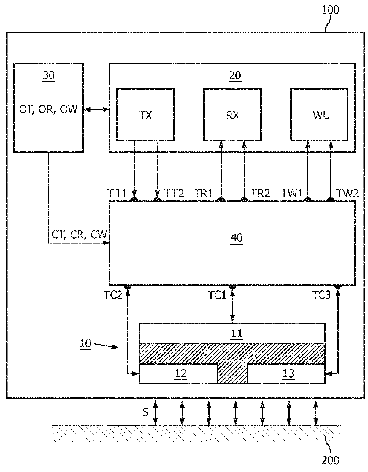
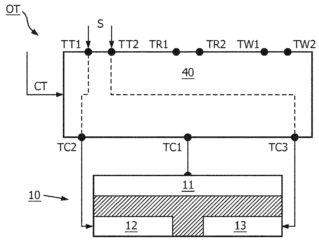
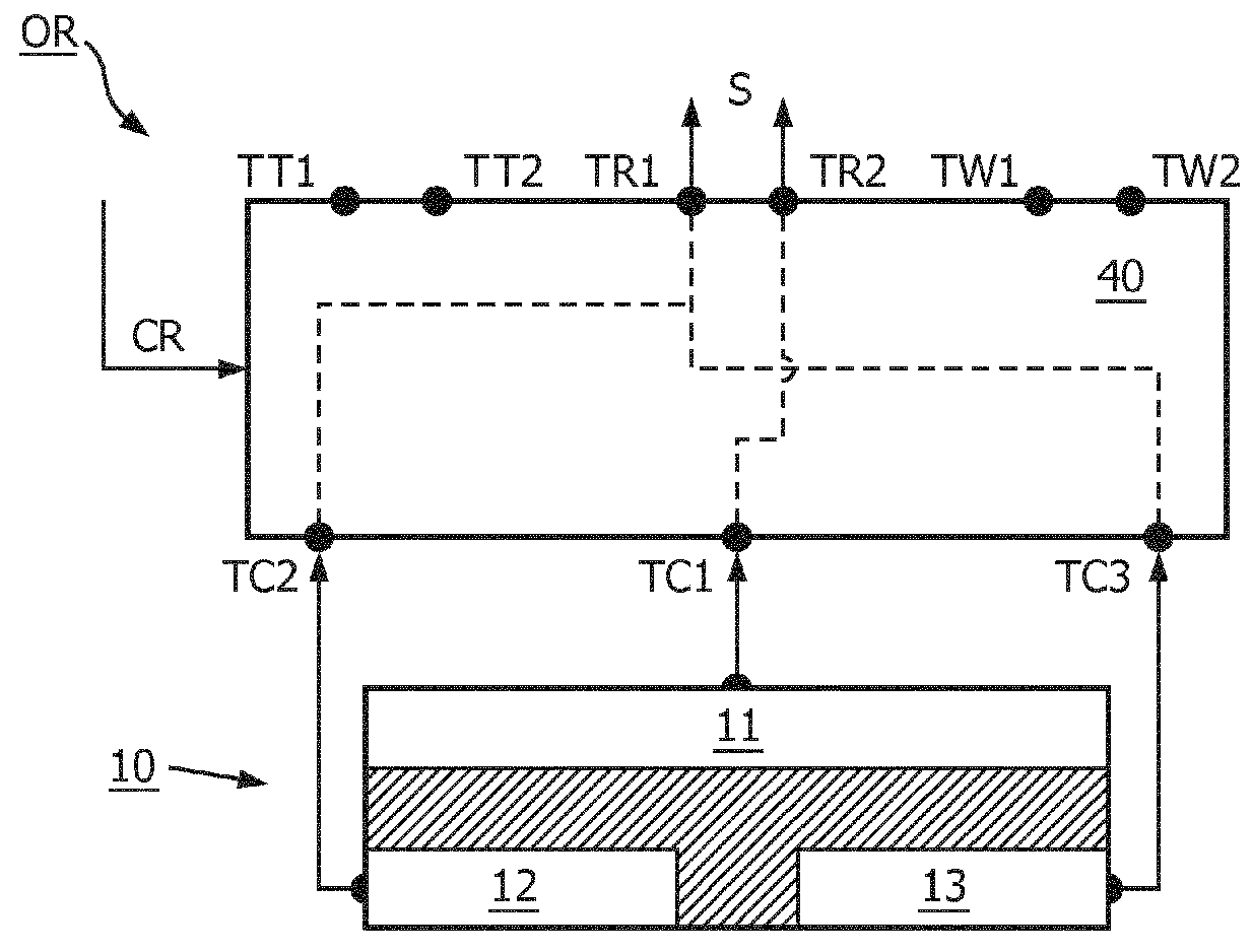
[0021]FIG. 1 shows a schematic embodiment of a body-coupled communication apparatus 100. The apparatus is configured to be placed at or in close proximity to a human or animal body 200 for transmitting and / or receiving signals S via the body 200. In one embodiment, the apparatus comprises a coupler arrangement 10 comprising a plurality of couplers 11,12,13 configured to couple the signals S between th...


PUM


Abstract

A body-coupled communication apparatus (100) comprises a coupler arrangement (10) comprising a plurality of couplers (11,12,13) configured to couple signals (S) between the apparatus (100) and a body (200). Signal electronics (20) are configured to process and/or generate the signals depending on an operational mode (OT,OR,OW) of the apparatus. A routing network (40) is configured to provide variable routing of the signals (S) between the signal electronics (20) and the couplers (11,12,13) thereby providing a selection between distinct coupling modes (CT,CR,CW) of the coupler arrangement (10). A mode selector (30) is configured to switch the apparatus (100) between the operational modes (OT,OR,OW) and control the routing network (40) to select between the distinct coupling modes (CT,CR,CW) based on the operational mode (OT,OR,OW) of the apparatus.

Description

TECHNICAL FIELD AND BACKGROUND[0001]The present disclosure relates to the field of body-coupled communication, in particular to an apparatus and a method for body-coupled communication.[0002]Body-Coupled Communication (BCC) is an emerging near field communication technology that uses the human (or animal) body to propagate data by wireless communication over the body between devices that are on or in close proximity with the body. The BCC technology has several important characteristics that make it particularly suitable for a wide range of wearable consumer and medical devices. For example, it can address the needs that the current communication approaches struggle with: ease-of-use, privacy, security, high data rate with high energy efficiency[0003]Current BCC devices use couplers that for some applications offer a good performance while for other applications can lead to an excessive use of energy, either to transmit higher signal levels, or to detect very low signal levels. On t...

Claims


Application Information

Patent Timeline
Patent Type & Authority Patents(United States)
IPC IPC(8): H04B5/00H04W52/02H04W40/00H04B13/00
CPCH04B13/005H04W52/0235H04W40/005H04B5/0012H04B13/00Y02D30/70
Inventor OUZOUNOV, SOTIR FILIPOV
Owner KONINKLJIJKE PHILIPS NV
Why Eureka
Try Eureka