Device and method for connecting an electric power generator to an HVDC transmission system

a transmission system and electric power technology, applied in the field of electric power production, can solve the problems of consuming reactive power, consuming technical difficulty, and often high cost, and reducing the reliability of the transmission system, so as to achieve less expensive, less expensive, and reliable and energy-saving

Active Publication Date: 2017-02-21
SIEMENS GAMESA RENEWABLE ENERGY AS
View PDF8 Cites 1 Cited by
  • Summary
  • Abstract
  • Description
  • Claims
  • Application Information

AI Technical Summary

Benefits of technology

[0012]This aspect of the invention is based on the idea that the connection between the electric power generator and the HVDC transmission system is split up in a first path (formed by the first unit) and a second path (formed by the second unit). The first path serves to convert the AC output voltage from the electric power generator to a suitable DC input voltage for the HVDC transmission system, i.e. the first unit comprises a transformer for increasing the AC voltage and a full-bridge rectifier that rectifies the increased AC voltage level to the DC input voltage for the HVDC transmission system. Thus, the first unit handles the actual (or main) transmission of electric power from the electric power generator into the HVDC transmission system. The second path serves to generate control / voltages and / or control currents, i.e. the second unit comprises a PWM full-bridge converter that is dedicated to performing control and correction functions rather than power transmission. In other words, the power transmission is handled by the simple and cost-effective full-bridge rectifier of the first unit, while control and correction functions are handled by a PWM full-bridge converter. As the PWM full-bridge converter of the second unit will not have to handle the same level of power as the full-bridge rectifier of the first unit, the PWM full-bridge converter of the second unit does not need to be nearly as complex (and thus expensive) as a PWM full-bridge converter designed to handle both power transmission and control functions. Accordingly, the device according to this aspect of the present invention provides a simple and cost-effective way of the feeding power from an electric power generator, such as an offshore wind turbine or wind farm, into a HVDC transmission system.
[0046]Or stated otherwise: This invention aims at creating an alternative HVDC topology. The core of the new topology is to allow the main power to flow through passive or low switching HVDC / MVDC converter system, while keeping the converters for active control at low voltage levels. Hence, in the high voltage path, simple power components (such as Thyristors or diodes) can be used, where the technology is relatively matured, and the resultant converter will be more reliable and energy efficient, but less expensive. The auxiliary parts are operated at low voltage for active control of power flow, as well as some critical functions such as voltage balancing across generators (e.g. wind turbines).

Problems solved by technology

With the development of large offshore wind farms for producing electric energy, transmission losses occurring along transmission lines between a wind farm and a connection to a distribution grid on land may become significant.
However, in order to handle the high voltage and high power in the HVDC transmission, especially under increasingly stringent performance requirements, some sophisticated power converter systems have to be applied, which can be technically challenging and often means high cost.
It consumes reactive power and the AC currents contain low-frequency harmonics.
Both systems employ multilevel converter techniques in order to accommodate low voltage rated power components (e.g., IGBT) and relatively low switching operations, and hence the systems tend to be relatively more technically challenging and more expensive.

Method used


Image

  • Device and method for connecting an electric power generator to an HVDC transmission system
  • Device and method for connecting an electric power generator to an HVDC transmission system
  • Device and method for connecting an electric power generator to an HVDC transmission system

Examples


Embodiment Construction

[0056]The illustration in the drawing is schematic. It is noted that in different figures, similar or identical elements are provided with the same reference numerals or with reference numerals which differ only within the first digit.

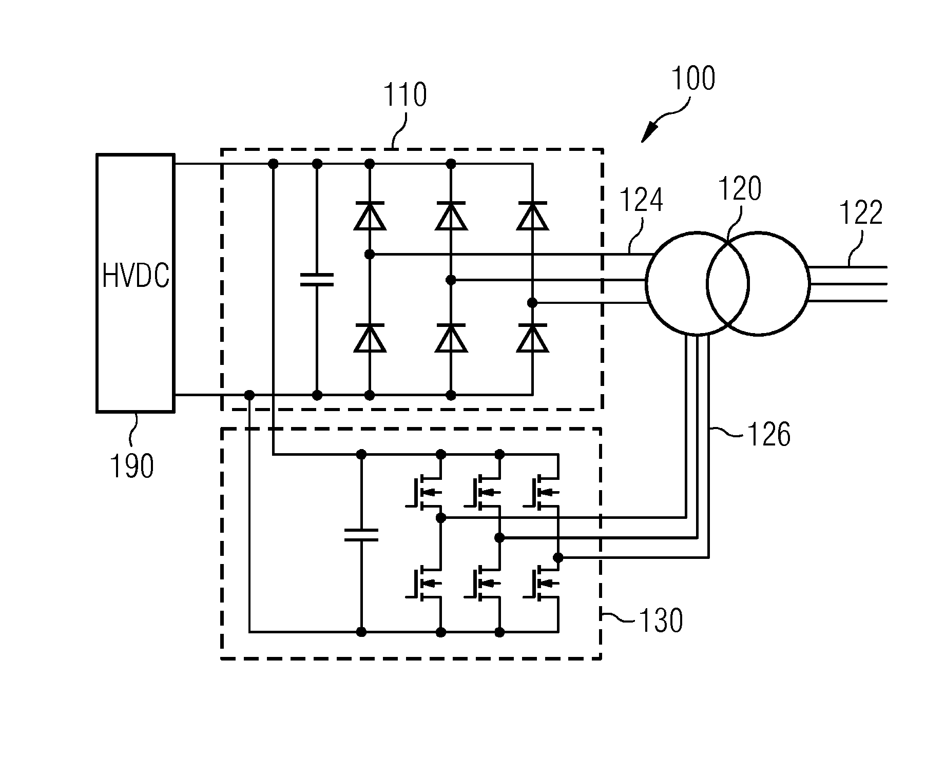
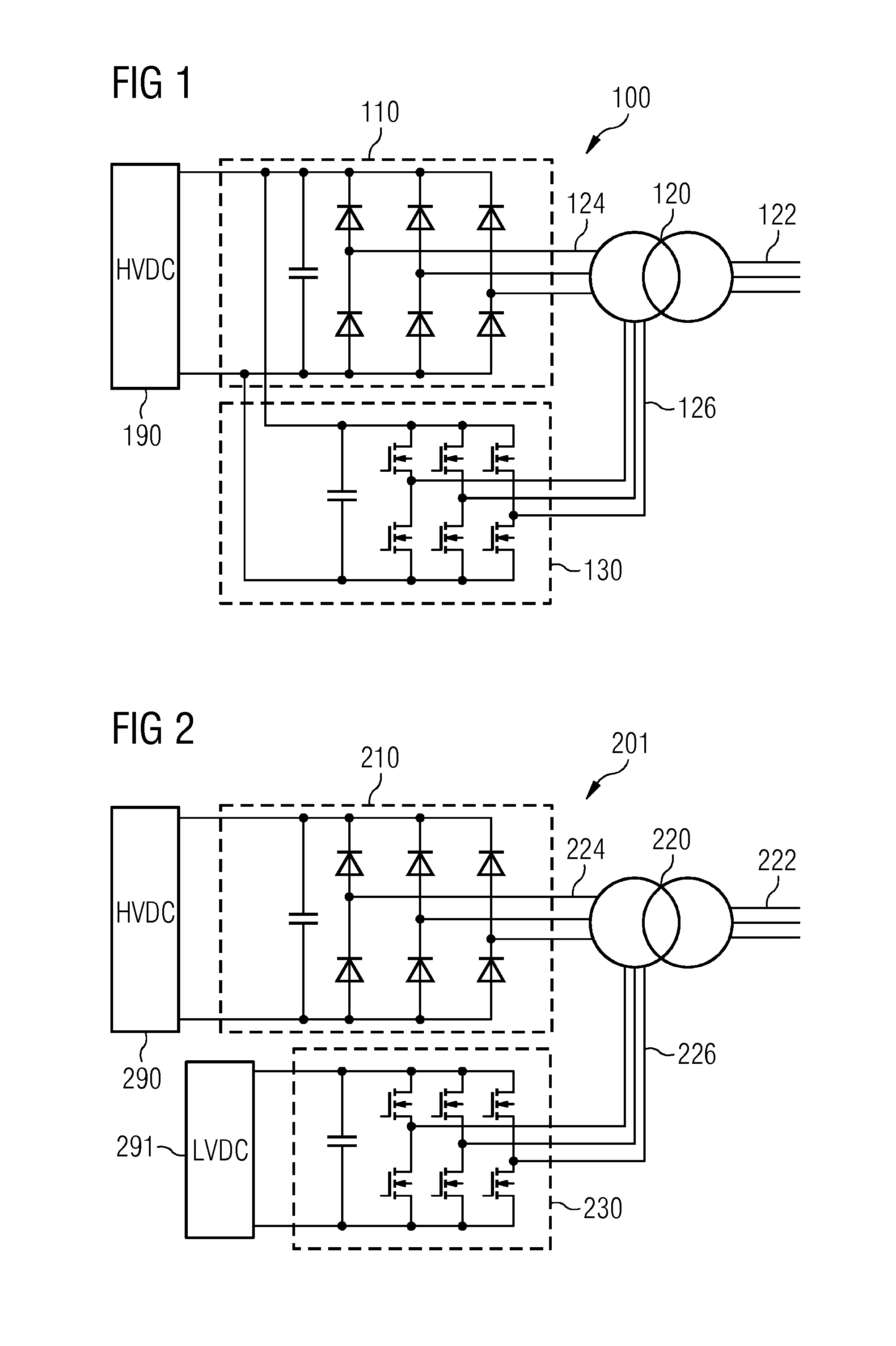
[0057]FIG. 1 shows a device 100 according to an embodiment of the present invention. The device 100 comprises a full-bridge rectifier 110, a step-up transformer 120, and a PWM full-bridge converter 130. The full-bridge rectifier 110 comprises six diodes (or thyristors) arranged to rectify a 3-phase AC input into an output DC voltage. The PWM full-bridge converter 130 is an active converter comprising semiconductor switching components (e.g. IGBTs) and a control circuit (not shown) for converting a 3-phase AC input into an output DC voltage while generating control currents and / or control voltages in the transformer 120. The transformer 120 comprises a set of 3 primary windings that is connectable to a 3-phase AC output from a generator, such as one or ...


PUM


Abstract

A device for connecting an electric power generator to an HVDC transmission system is provided, the device having (a) a first unit for converting an AC output voltage from the electric power generator to a DC input voltage for the HVDC transmission system, the first unit having a transformer and a full-bridge rectifier, and (b) a second unit for generating control voltages and / or control currents in the transformer and / or in the electric power generator, the second unit having a PWM full-bridge converter adapted to receive the AC output voltage from the electric power generator or an AC voltage based on said AC output voltage. Furthermore, a system and a method are provided.

Description

CROSS REFERENCE TO RELATED APPLICATIONS[0001]This application claims the benefit of European Application No. EP14170792 filed Jun. 2, 2014, incorporated by reference herein in its entirety.FIELD OF INVENTION[0002]The present invention relates to the field of electrical power production, in particular to devices and methods for connecting electric power generators to an HVDC transmission system.ART BACKGROUND[0003]With the development of large offshore wind farms for producing electric energy, transmission losses occurring along transmission lines between a wind farm and a connection to a distribution grid on land may become significant.[0004]In such cases, HVDC (high-voltage, direct current) technology has distinct advantages in terms of low losses in comparison to the common AC (alternating current) technologies. In particular, by using a high voltage (up to e.g. 800 kV), the current flowing in the transmission lines—and thereby the resistive losses—is significantly reduced when a ...

Claims


Application Information

Patent Timeline
Patent Type & Authority Patents(United States)
IPC IPC(8): H02J3/36H02M5/458
CPCH02M5/458H02J3/36H02J2003/365Y02E10/76Y02E60/60H02M7/08Y02B70/10H02M1/4283
Inventor PETERSEN, JESPER ELLIOTTHOMAS, ARWYNWU, ZHAN-YUANXIA, ZHEN PING
Owner SIEMENS GAMESA RENEWABLE ENERGY AS
Why Eureka
Try Eureka