Alarm mat

a technology of alarm mats and insulating plates, applied in the field of alarm mats, can solve the problems of large area of elastic plates where cavities are formed, time-consuming production process and large production costs, and the airflow through the cavities through the whistles is possibly too weak to make the whistles produce sound, etc., and achieves the effect of less production costs

Active Publication Date: 2015-08-25
DAIFUKU CO LTD
View PDF15 Cites 2 Cited by
  • Summary
  • Abstract
  • Description
  • Claims
  • Application Information

AI Technical Summary

Benefits of technology

[0008]To solve these conventional technical problems, the invention provides a non-electric alarm mat producible with less production costs than the conventional products, wherein it is ensured that sound producers produce sound.
[0017]According to the alarm mat provided by the invention, when any of the projections is stepped on by foot, the projection is compressed and deformed, and air inside of the projection flows out. At the time, the sound producer produces sound. Once the foot is removed from the projection, the projection compressed and deformed is immediately elastically restored, which introduces air into the projection. Then, the sound producer produces sound again. When the alarm mat is stepped on continuously, the projection is accordingly compressed and deformed, and the sound producer keeps producing sound. The invention, wherein number of structural elements is largely reduced than the prior art products, can easily produce the alarm mat and reduces production and maintenance costs.
[0018]According to the alarm mat wherein the holders are provided, the holders prevent the sound producers from being crushed by the foot placed on edges of the projections where the sound producers are provided. According to the alarm mat wherein the upper surface cover member is colored differently to the cover sheet, an area of danger is more visually noticeable.

Problems solved by technology

The prior arts 1 and 2, wherein it is necessary to set the sealed tubular members and the whistles in a large number of projections, requires extensive man-hours during the production of these mats, leading to a time-consuming production process and large production costs.
This structural disadvantage involves the risk that airflow leaking from the cavities through the whistles is possibly too weak to make the whistles produce sound.
The prior art 3 has another disadvantage that the elastic plate where the cavities are formed has a large area.
Such a large plate, when stepped on by foot, does not immediately regain its original shape, therefore, there are times when the whistles fail to produce sound.

Method used


Image

  • Alarm mat
  • Alarm mat
  • Alarm mat

Examples


Embodiment Construction

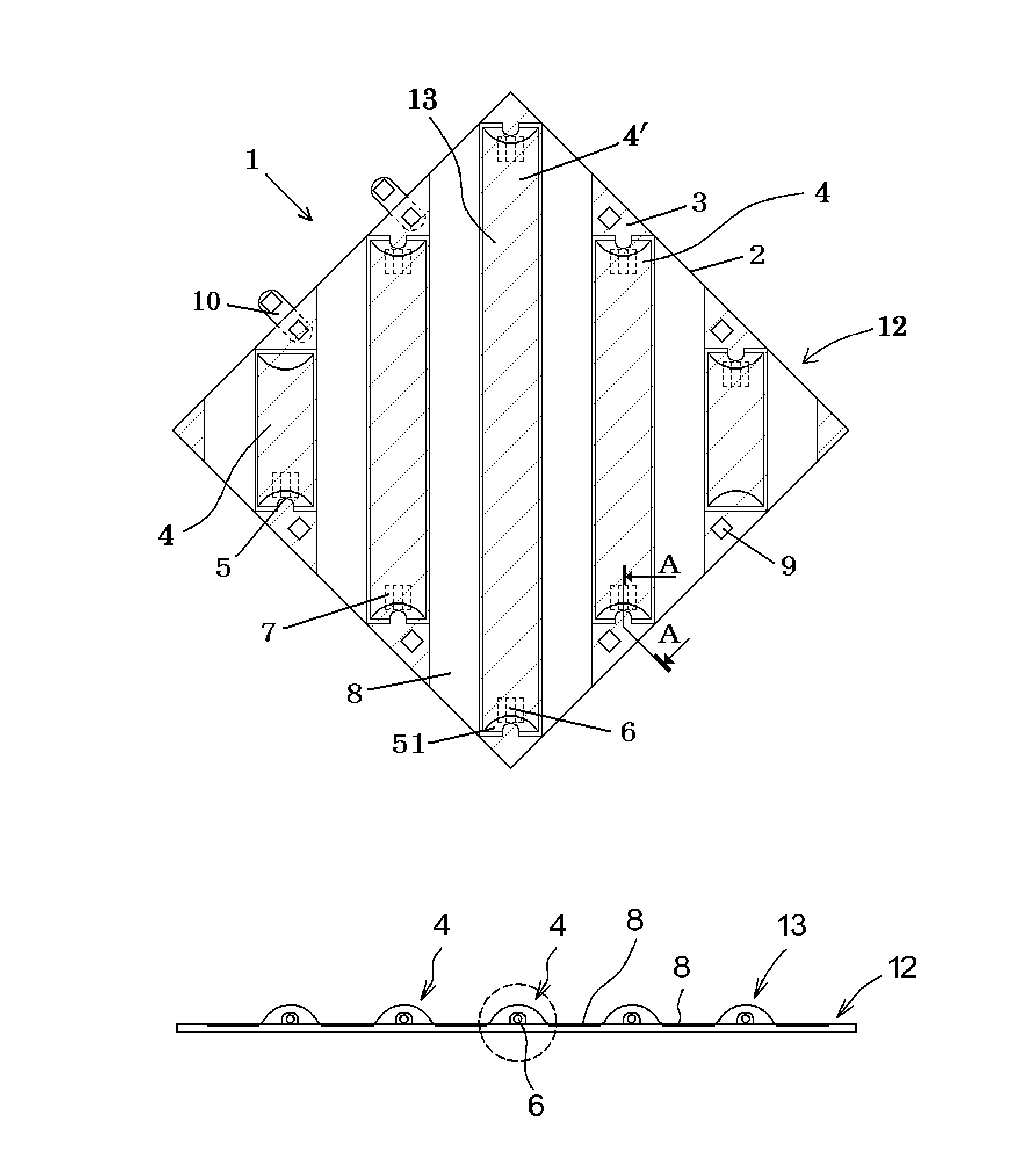
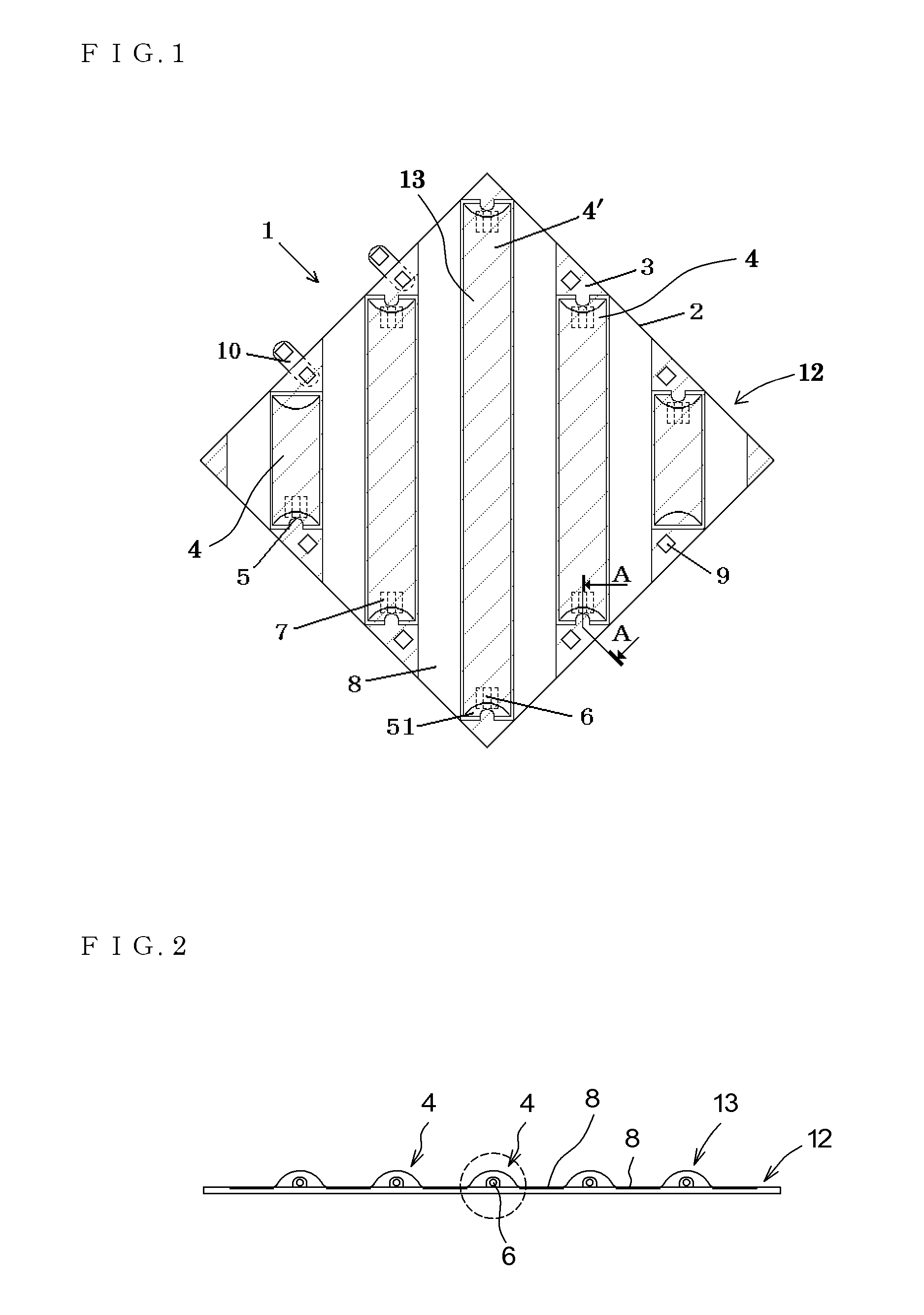
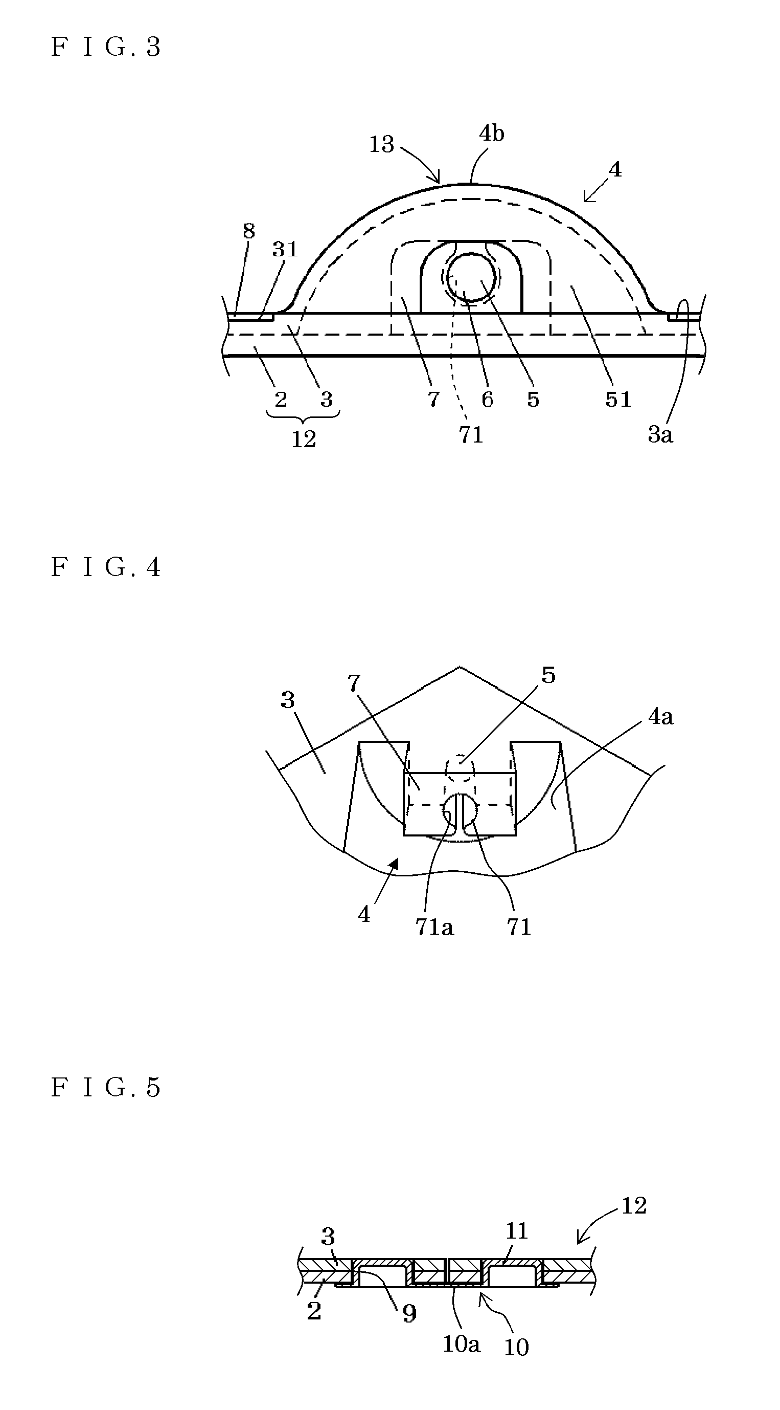
[0032]Hereinafter, an exemplary embodiment of the invention is described in detail referring to the drawings. FIGS. 1 and 2 are planar and front views of an alarm mat 1 according to an exemplary embodiment of the invention. Referring to these drawings, the alarm mat 1 has a medium 2 having a flat and rectangular plate shape and made of an elastic material such as a rubber material or a synthetic resin. An area of the medium 2 from a side surface to an upper surface thereof is covered with a cover sheet 3 made of a rubber material or a synthetic resin more flexible than the material of the medium 2. The cover sheet 3 is adhered to the medium 2 with a double stick tape or an adhesive. The medium 2 and the cover sheet 3 constitute a sheet 12.

[0033]The cover sheet 3 has a plurality of semi-cylindrical projection bodies 4 each having a dented inside and projecting toward an upper-surface side of the sheet. The cover sheet 3 and the projection bodies 4 are integrally formed. The projectio...


PUM


Abstract

An alarm mat includes a sheet, and sound producer from which sound is produced by air inflow and outflow. The sheet is provided with a plurality of projections made of an elastic material, projecting toward an upper-surface side of the sheet with top portions thereof continuously extending, and each having a sealed cavity inside. The plurality of projections are juxtaposed to each other. The sound producer is loaded in the sheet in a manner that air flows in and out of the projections through the sound producer alone.

Description

BACKGROUND OF THE INVENTION[0001]1. Field of the Invention[0002]The invention relates to an alarm mat laid on a floor surrounding a dangerous area not to be accessed in, for example, plants and construction sites.[0003]2. Description of the Related Art[0004]Japan Patent No. 2751659 (hereinafter, called prior art 1) discloses an alarm mat provided with a large number of semispherical projections provided on a base plate including a plywood board, sealed tubular members formed in a bellows-like shape in cavities of the projections, and whistles sounded by air inflow and outflow to and from the sealed tubular members. This alarm mat needs no power supply.[0005]Japan Patent No. 2903854 (hereinafter, called prior art 2) discloses an alarm mat provided with a large number of semispherical projections elastically deformable and provided on a base plate including a plywood board, sealed tubular members formed in the projections, whistles sounded by the deformation of the sealed tubular memb...

Claims


Application Information

Patent Timeline
Patent Type & Authority Patents(United States)
IPC IPC(8): G08B13/10F16P3/12G08B21/02A63B5/00G08B3/06
CPCF16P3/12A63B5/00G08B3/06G08B13/10G08B21/02
Inventor IDO, MINEO
Owner DAIFUKU CO LTD
Why Eureka
Try Eureka